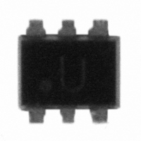
USBUF01P6 STMicroelectronics, USBUF01P6 Datasheet

USBUF01P6
Specifications of USBUF01P6
Available stocks
Related parts for USBUF01P6
USBUF01P6 Summary of contents
Page 1
... FCC regulations. In addition to the requirements of termination and EMC compatibility, the computing devices are required to be tested for ESD susceptibility. The USBUF01P6 provides the recommended line termination while implementing a low pass filter to limit EMI levels and providing ESD protection which exceeds IEC 61000-4-2 level 4 standard. ...
Page 2
... Parameter IEC 61000-4-2 air discharge IEC 61000-4-2 contact discharge MIL STD 883E - Method 3015 °C) amb Parameter Test conditions Min 3.3 V per line RM Tolerance ± 10% Tolerance ± 10% Tolerance ± 20% Doc ID 9883 Rev 7 USBUF01P6 Value ± 16 ± 9 ± 25 150 -55 to +150 260 - ...
Page 3
... Rd D+ out D+ Gnd out LOW SPEED CONNECTION Doc ID 9883 Rev 7 Technical information 3.3V 1. Full-speed USB Ct Transceiver Hub 0 or Full-speed function 3.3V 1. Low-speed USB Ct Transceiver Hub 0 or Low-speed function USBUF01P6 Upstream port D+ D2 GND 3 3.3V USBUF01P6 Upstream port D+ D2 GND 3 3.3V 3/9 ...
Page 4
... Conducted EMI covers the 450 kHz to 30 MHz range. For the types of device compliant with the USB standard, the most difficult test to pass is usually the radiated EMI test. For this reason the USBUF01P6 device aims to minimize radiated EMI. The differential signal (D+ and D-) of USB devices does not contribute significantly to radiated or conducted EMI because the magnetic field of each conductor cancels out the other ...
Page 5
... ESD susceptibility. This test is described in IEC 61000-4-2 and is already in place in Europe. This test requires that a device tolerates ESD events and remains operational without user intervention. The USBUF01P6 is particularly optimized to perform ESD protection. ESD protection is based on the use of device which clamps at: V ...
Page 6
... S2 (V input positive ESD surge Note: The USBUF01P6 acts not only for positive ESD surges but also for negative ones. For these kinds of disturbances it clamps close to ground voltage as shown in 6/9 side due the low current involved after the resistance R output ...
Page 7
... USBUF01P6 3 Package information ● Epoxy meets UL94, V0 ● Lead-free package In order to meet environmental requirements, ST offers these devices in different grades of ® ECOPACK packages, depending on their level of environmental compliance. ECOPACK specifications, grade definitions and product status are available at: www.st.com. ® ECOPACK trademark. Table 3. ...
Page 8
... Typing error in table 2 on page 2: change W and kW unit 6 to and k unit. Updated GND pin annotation in Figures pin numbering indication to illustration and updated 7 dimension values in specifications in Doc ID 9883 Rev 7 USBUF01P6 Base qty Delivery mode 3000 Tape and reel Changes 1 and 3. Added Table 3. Updated mechanical Section 3 ...
Page 9
... USBUF01P6 Information in this document is provided solely in connection with ST products. STMicroelectronics NV and its subsidiaries (“ST”) reserve the right to make changes, corrections, modifications or improvements, to this document, and the products and services described herein at any time, without notice. All ST products are sold pursuant to ST’s terms and conditions of sale. ...


