CS82C54-10 Intersil, CS82C54-10 Datasheet - Page 20
CS82C54-10
Manufacturer Part Number
CS82C54-10
Description
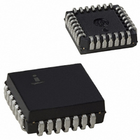
IC TIMER PROG CMOS 10MHZ 28-PLCC
Manufacturer
Intersil
Type
Programmable Timerr
Datasheet
1.CS82C54Z96.pdf
(22 pages)
Specifications of CS82C54-10
Frequency
10MHz
Voltage - Supply
4.5 V ~ 5.5 V
Current - Supply
10mA
Operating Temperature
0°C ~ 70°C
Package / Case
28-PLCC
Lead Free Status / RoHS Status
Contains lead / RoHS non-compliant
Count
-
Available stocks
Company
Part Number
Manufacturer
Quantity
Price
Company:

Part Number:
CS82C54-10
Manufacturer:
HAR/INT
Quantity:
8 000
Company:
Part Number:
CS82C54-10
Manufacturer:
HAR/INT
Quantity:
8 000
Company:
Part Number:
CS82C54-10
Manufacturer:
HARRIS
Quantity:
35
Company:
Part Number:
CS82C54-10
Manufacturer:
INTERSIL
Quantity:
2 770
Part Number:
CS82C54-10
Manufacturer:
INTERSIL
Quantity:
20 000
Company:
Part Number:
CS82C54-10Z
Manufacturer:
Intersil
Quantity:
9 444
Part Number:
CS82C54-10Z
Manufacturer:
INTERSIL
Quantity:
20 000
Part Number:
CS82C54-10Z96
Manufacturer:
INTERSIL
Quantity:
20 000


Plastic Leaded Chip Carrier Packages (PLCC)
0.020 (0.51) MAX
3 PLCS
NOTES:
0.042 (1.07)
0.048 (1.22)
1. Controlling dimension: INCH. Converted millimeter dimensions are
2. Dimensions and tolerancing per ANSI Y14.5M-1982.
3. Dimensions D1 and E1 do not include mold protrusions. Allowable
4. To be measured at seating plane
5. Centerline to be determined where center leads exit plastic body.
6. “N” is the number of terminal positions.
not necessarily exact.
mold protrusion is 0.010 inch (0.25mm) per side. Dimensions D1
and E1 include mold mismatch and are measured at the extreme
material condition at the body parting line.
PIN (1) IDENTIFIER
0.045 (1.14)
MIN
C L
D1
D
0.026 (0.66)
0.032 (0.81)
0.050 (1.27) TP
VIEW “A” TYP.
20
0.042 (1.07)
0.056 (1.42)
E1
-C-
E
C L
0.025 (0.64)
MIN
0.013 (0.33)
0.021 (0.53)
contact point.
A
A1
-C-
0.004 (0.10)
D2/E2
D2/E2
0.025 (0.64)
0.045 (1.14)
SEATING
PLANE
VIEW “A”
0.020 (0.51)
MIN
R
82C54
C
N28.45
28 LEAD PLASTIC LEADED CHIP CARRIER PACKAGE
SYMBOL
A1
D1
D2
E1
E2
D
N
A
E
(JEDEC MS-018AB ISSUE A)
0.165
0.090
0.485
0.450
0.191
0.485
0.450
0.191
MIN
INCHES
28
MAX
0.180
0.120
0.495
0.456
0.219
0.495
0.456
0.219
12.32
11.43
12.32
11.43
MILLIMETERS
4.20
2.29
4.86
4.86
MIN
28
12.57
11.58
12.57
11.58
MAX
4.57
3.04
5.56
5.56
Rev. 2 11/97
NOTES
4, 5
4, 5
3
3
6
-
-
-
-
Related parts for CS82C54-10
Image
Part Number
Description
Manufacturer
Datasheet
Request
R

Part Number:
Description:
IC TIMER INTERVAL 10MHZ 28-PLCC
Manufacturer:
Intersil
Datasheet:
Part Number:
Description:
IC TIMER PROG CMOS 8MHZ 28-PLCC
Manufacturer:
Intersil
Datasheet:
Part Number:
Description:
IC TIMER PROGR 5V 10MHZ 28-PLCC
Manufacturer:
Intersil
Datasheet:
Part Number:
Description:
IC TIMER PROGR 5V 12.5MHZ 28PLCC
Manufacturer:
Intersil
Datasheet:
Part Number:
Description:
IC TIMER PROGR 5V 12.5MHZ 28PLCC
Manufacturer:
Intersil
Datasheet:
Part Number:
Description:
IC TIMER PROGR 5V 10MHZ 28-PLCC
Manufacturer:
Intersil
Datasheet:
Part Number:
Description:
IC TIMER PROGR 5V 12.5MHZ 28PLCC
Manufacturer:
Intersil
Datasheet:

Part Number:
Description:
Intersil Corporation [CMOS Serial Controller Interface]
Manufacturer:
Intersil Corporation
Datasheet:
Part Number:
Description:
Manufacturer:
Intersil Corporation
Datasheet:
Part Number:
Description:
357-036-542-201 CARDEDGE 36POS DL .156 BLK LOPRO
Manufacturer:
Intersil Corporation
Datasheet:
Part Number:
Description:
1024-Word x 4-Bit LSI Static RAM
Manufacturer:
Intersil Corporation
Datasheet:
Part Number:
Description:
General Purpose NPN Transistor Arrays FN341.4
Manufacturer:
Intersil Corporation
Datasheet:
Part Number:
Description:
CMOS 16-Bit Microprocessor
Manufacturer:
Intersil Corporation
Datasheet:
Part Number:
Description:
Manufacturer:
Intersil Corporation
Datasheet:
Part Number:
Description:
Manufacturer:
Intersil Corporation
Datasheet: