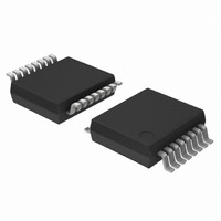
74LV4799DB,112 NXP Semiconductors, 74LV4799DB,112 Datasheet - Page 4

74LV4799DB,112
Manufacturer Part Number
74LV4799DB,112
Description
IC TIMER NICD/NIMH CHRGR 16-SSOP
Manufacturer
NXP Semiconductors
Type
Timer Controlr
Series
74LVr
Datasheet
1.74LV4799SD118.pdf
(18 pages)
Specifications of 74LV4799DB,112
Package / Case
16-SSOP
Frequency
100kHz
Voltage - Supply
0.9 V ~ 6 V
Current - Supply
36µA
Operating Temperature
0°C ~ 70°C
Supply Voltage (max)
6 V
Supply Voltage (min)
0.9 V
Maximum Operating Temperature
+ 70 C
Minimum Operating Temperature
0 C
Mounting Style
SMD/SMT
Lead Free Status / RoHS Status
Lead free / RoHS Compliant
Count
-
Lead Free Status / RoHS Status
Lead free / RoHS Compliant, Lead free / RoHS Compliant
Other names
568-2981-5
935175040112
935175040112
Philips Semiconductors
PIN DESCRIPTION
Power On Reset.
An automatic Power On Reset initiates the IC when the battery is
discharged and power is connected to the circuit. The initial
condition is the charge mode in which the counter is reset and
counts from zero up to maximum. At start up, the battery therefore
always receives a full charge cycle. When a partially charged battery
is inserted, it may be over-charged during the first cycle. To guard
against this, simply replace the resistor at the R
type which is in good thermal contact with the battery. If the
temperature of the battery increases, the frequency of the oscillator
also increases to quickly reach a counter full indication and
switch-over to trickle charge. With a battery that is almost
completely discharged, the POR input can also be activated during
discharge or self-discharge. The counter will then be reset to zero.
This is a correct action while returning to the initial condition.
Power-on sensing.
Because this IC supports virtually all battery chargers, the PWRS input
has a broad input frequency spectrum (active HIGH to 100 kHz). A
pull-down circuit at the PWRS input allows detection of the open state
which corresponds to an inactive charger. A HIGH level on the PWRS
input, or an AC signal up to 100 kHz, enables the charge mode.
Start-up with low battery voltage.
Good start-up, even with an un-charged battery, is assured by using
the V
bipolar transistors at the EN or EN output, even if the IC is not yet
functioning. After the battery has received sufficient charge, the
internal control logic takes over control of the EN and EN outputs.
Charge mode.
This mode is selected when PWRS is active (HIGH or pulsed) and
the discharge input DIS is HIGH. The EN output is HIGH, and the
EN output is LOW initiating continuous charge of the battery. The
counter then counts from the zero state up to the maximum value.
The clock frequency is determined by the external capacitor and
resistor connected to the R
1998 Apr 20
PIN NO.
Timer for NiCd and NiMH chargers
10
12
13
14
15
16
IN
11
1
2
3
4
5
6
7
8
9
input. The voltage on the V
LED
EN
EN
V
PWRS
MOLLI/SCO
SEL
GND
DIS
R
R
R
I
SCAN
SCI
V
OSC
in
CC
C
D
S
SYMBOL
C
output. The counter stops when it
IN
input biases the external
LED driver output pin (active LOW)
Enable output (active HIGH)
Enable output (active LOW)
External power input
Power sense input
More-or-less-low-indication output (active LOW)/scan test output
LED mode select input
Ground (0 V)
Discharge input (active LOW)
External resistor pin 3-State oscillator output (charge)
External resistor pin 3-State output (discharge)
External resistor pin 3-State output (self-discharge)
Oscillator input
Scan test mode select input (active HIGH)
Scan test input
Positive supply voltage
C
pin with an NTC
4
reaches its maximum value and the EN and EN outputs switch over
from the continuous charge to the trickle charge mode.
Trickle charge mode.
At the maximum counter value, it is assumed that the battery is fully
charged. The counter stops and remains on this maximum value.
The EN and EN outputs switch over from the continues charge to
the trickle charge mode. In the trickle charge mode, the average
charge current is reduced to only compensate the self-discharge of
the battery by using the dedicated duty cycle control. The control is
dedicated because it adjusts the duty cycle in inverse proportion to
the load current, resulting in a fixed charger current irrespective of
the kind of charger (e.g. 4-hour or 16-hour charger). In the trickle
charge mode, the oscillator circuitry alternately generates 4 periods
of R
(See Figure 1).
Discharge mode.
The discharge input (DIS) is used to detect the discharge of the
battery. If DIS is LOW, the counter counts down. The clock
frequency is determined by the external capacitor and resistor at the
R
LOW, and the EN output is in the high impedance OFF-state (no
charge of the battery). This is called the discharge mode. If PWRS is
active, the circuit is in the charge/discharge mode.
Charge/Discharge mode.
If DIS is LOW and PWRS is active (HIGH or pulsed), the circuit is in
the charge/discharge mode. The counter counts down. The clock
frequency is determined by the external capacitor and resistor tied
at the R
initiating continuous charge of the battery. The battery is therefore
charged and discharged at the same instant, thereby maintaining a
better load condition of the battery.
D
output. If PWRS is inactive (LOW or open), the EN output is
C
-C1 time-constant, and 3 periods of the R
NAME AND FUNCTION
D
output. The EN output is HIGH, and the EN output is LOW
S
Product specification
74LV4799
-C1 time-constant


