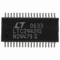
LTC2442IG#PBF Linear Technology, LTC2442IG#PBF Datasheet - Page 26

LTC2442IG#PBF
Manufacturer Part Number
LTC2442IG#PBF
Description
IC ADC 24BIT 4CH 36-SSOP
Manufacturer
Linear Technology
Datasheet
1.LTC2442CGPBF.pdf
(32 pages)
Specifications of LTC2442IG#PBF
Number Of Bits
24
Sampling Rate (per Second)
8k
Data Interface
MICROWIRE™, Serial, SPI™
Number Of Converters
1
Power Dissipation (max)
50mW
Voltage Supply Source
Single Supply
Operating Temperature
-40°C ~ 85°C
Mounting Type
Surface Mount
Package / Case
36-SSOP (0.200", 5.30mm Width)
Lead Free Status / RoHS Status
Lead free / RoHS Compliant
Available stocks
Company
Part Number
Manufacturer
Quantity
Price
LTC2442
APPLICATIO S I FOR ATIO
The LTC2442 breaks new ground in high impedance input
ΔΣ ADCs. The input buffer is optimized to make driving
the ADC as easy as possible, while overcoming many of
the limitations typical of integrated buffers.
Convenient +5V to –5V/+9V DC-DC Converter
If either of the signal inputs must include ground and
V
greater than the maximum input voltage and a negative
supply. Figure 19 shows how to derive both –5V and +9V
from a single 5V supply using an LTC1983, allowing the
ADC inputs to extend as much as 300mV below ground
and above V
not go within 1.5V of V
be eliminated and the amplifi er positive supply can be
connected to V
26
CC
, then the amplifi er will require both a positive supply
CC
CC
. For inputs that include ground but do
.
U
CC
U
, then C4, C5, C6 and D1 can
4.7µF
W
C1
5V
Figure 19. LTC1983 with Another Charge
Pump Stacked onto V
U
1
6
3
C4
2.2µF
LTC1983ES6-5
V
SHDN
C
CC
+
2.2µF
C3
D1
BAT54S
V
GND
OUT
Input Bias Current
The 10nA typical bias current of the buffers results in less
than 1ppm (5µV) error for source resistance imbalances
of less than 500Ω. Matching the resistance at the inputs
cancels much of the error due to amplifi er bias current.
For source resistances up to 50k, 1% resistors are ad-
equate. Figure 20 shows proper input resistance matching
for a precision voltage divider on the CH2-3 inputs. The
resistance seen by CH2 is the parallel combination of 30k
and 10k or 7.5k. A 1%, 7.5k resistor at CH3 balances the
resistance of the divider output.
While the two input buffers will have slightly different
bias currents, the autozero process applies the bias cur-
rent from each buffer to both of the inputs for half of the
conversion time, so the offset is equal to the average
of the two bias currents multiplied by the mismatch in
source resistance.
C
–
CC
2
5
4
to Give 9V
C5
2.2µF
C2
4.7µF
C6
4.7µF
2442 F19
–5V
9V
2442f


