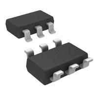
ADC101C021CIMKX/NOPB National Semiconductor, ADC101C021CIMKX/NOPB Datasheet - Page 21

ADC101C021CIMKX/NOPB
Manufacturer Part Number
ADC101C021CIMKX/NOPB
Description
IC ADC 10BIT SAR I2C TSOT-23-6
Manufacturer
National Semiconductor
Datasheet
1.ADC101C021CIMMNOPB.pdf
(30 pages)
Specifications of ADC101C021CIMKX/NOPB
Number Of Bits
10
Sampling Rate (per Second)
188.9k
Data Interface
I²C, Serial
Number Of Converters
1
Power Dissipation (max)
780µW
Voltage Supply Source
Single Supply
Operating Temperature
-40°C ~ 105°C
Mounting Type
Surface Mount
Package / Case
SOT-23-6 Thin, TSOT-23-6
For Use With
ADC101C02XEB - BOARD EVALUATION FOR ADC101C02X
Lead Free Status / RoHS Status
Lead free / RoHS Compliant
Other names
ADC101C021CIMKX
Please refer to the Philips I
2000) for a detailed description of the serial interface.
1.7.2 Standard-Fast Mode
In Standard-Fast mode, the master generates a start condi-
tion by driving SDA from high to low while SCL is high. The
start condition is always followed by a 7-bit slave address and
a Read/Write bit. After these 8 bits have been transmitted by
the master, SDA is released by the master and the
ADC101C021 either ACKs or NACKs the address. If the slave
address matches, the ADC101C021 ACKs the master. If the
address doesn't match, the ADC101C021 NACKs the master.
For a write operation, the master follows the ACK by sending
the 8-bit register address pointer to the ADC. Then the
ADC101C021 ACKs the transfer by driving SDA low. Next,
the master sends the upper 8-bits to the ADC101C021. Then
the ADC101C021 ACKs the transfer by driving SDA low. For
a single byte transfer, the master should generate a stop con-
dition at this point. For a 2-byte write operation, the lower 8-
bits are sent by the master. The ADC101C021 then ACKs the
transfer, and the master either sends another pair of data
bytes, generates a Repeated Start condition to read or write
another register, or generates a Stop condition to end com-
munication.
A read operation can take place either of two ways:
If the address pointer is pre-set before the read operation, the
desired register can be read immediately following the slave
address. In this case, the upper 8-bits of the register, set by
the pre-set address pointer, are sent out by the ADC. For a
single byte read operation, the Master sends a NACK to the
ADC and generates a Stop condition to end communication
after receiving 8-bits of data. For a 2-byte read operation, the
Master continues the transmission by sending an ACK to the
ADC. Then the ADC sends out the lower 8-bits of the ADC
register. At this point, the master either sends an ACK to re-
ceive more data or, a NACK followed by a Stop or Repeated
Start. If the master sends an ACK, the ADC sends the next
upper data byte, and the read cycle repeats.
If the ADC101C021 address pointer needs to be set, the mas-
ter needs to write to the device and set the address pointer
2
C
®
Specification (Version 2.1 Jan,
FIGURE 7. Basic Operation.
21
before reading from the desired register. This type of read
requires a start, the slave address, a write bit, the address
pointer, a Repeated Start (if appropriate), the slave address,
and a read bit (refer to Figure 12). Following this sequence,
the ADC sends out the upper 8-bits of the register. For a single
byte read operation, the Master must then send a NACK to
the ADC and generate a Stop condition to end communica-
tion. For a 2-Byte write operation, the Master sends an ACK
to the ADC. Then, the ADC sends out the lower 8-bits of the
ADC register. At this point, the master sends either an ACK
to receive more data, or a NACK followed by a Stop or Re-
peated Start. If the master sends an ACK, the ADC sends
another pair of data bytes, and the read cycle will repeat. The
number of data words that can be read is unlimited.
1.7.3 High-Speed (Hs) Mode
For Hs-mode, the sequence of events to begin communica-
tion differs slightly from Standard-Fast mode. Figure 8 de-
scribes this in further detail. Initially, the bus begins running
in
Start condition and sends the 8-bit Hs master code
(00001XXX) to the ADC101C021. Next, the ADC101C021
responds with a NACK. Once the SCL line has been pulled to
a high level, the master switches to Hs-mode by increasing
the bus speed and generating a second Repeated Start con-
dition (driving SDA low while SCL is pulled high). At this point,
the master sends the slave address to the ADC101C021, and
communication continues as shown above in the "Basic Op-
eration" Diagram (see Figure 7).
When the master generates a Repeated Start condition while
in Hs-mode, the bus stays in Hs-mode awaiting the slave ad-
dress from the master. The bus continues to run in Hs-mode
until a Stop condition is generated by the master. When the
master generates a Stop condition on the bus, the bus must
be started in Standard-Fast mode again before increasing the
bus speed and switching to Hs-mode.
Standard-Fast
mode.
The
master
generates
www.national.com
30052011
a


