ADC12H034CIMSA/NOPB National Semiconductor, ADC12H034CIMSA/NOPB Datasheet - Page 4
ADC12H034CIMSA/NOPB
Manufacturer Part Number
ADC12H034CIMSA/NOPB
Description
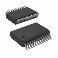
ADC 12BIT W/S&H +SIGN 24-SSOP
Manufacturer
National Semiconductor
Datasheet
1.ADC12030CIWMNOPB.pdf
(42 pages)
Specifications of ADC12H034CIMSA/NOPB
Number Of Bits
12
Data Interface
NSC MICROWIRE™, Serial
Number Of Converters
4
Power Dissipation (max)
33mW
Voltage Supply Source
Analog and Digital
Operating Temperature
-40°C ~ 85°C
Mounting Type
Surface Mount
Package / Case
24-SSOP (0.200", 5.30mm Width)
Number Of Elements
1
Architecture
SAR
Input Polarity
Unipolar
Input Type
Voltage
Rated Input Volt
5V
Differential Input
Yes
Power Supply Requirement
Analog and Digital
Single Supply Voltage (typ)
5V
Single Supply Voltage (min)
4.5V
Single Supply Voltage (max)
5.5V
Dual Supply Voltage (typ)
Not RequiredV
Dual Supply Voltage (min)
Not RequiredV
Dual Supply Voltage (max)
Not RequiredV
Power Dissipation
500mW
Differential Linearity Error
±1LSB
Integral Nonlinearity Error
±1LSB
Operating Temp Range
-40C to 85C
Operating Temperature Classification
Industrial
Mounting
Surface Mount
Pin Count
24
Package Type
SSOP
Lead Free Status / RoHS Status
Lead free / RoHS Compliant
Other names
ADC12H034CIMSA


www.national.com
Pin Name
DGND
CONV
AGND
CCLK
V
SCLK
V
EOC
DOR
V
V
CS
REF
PD
REF
DI
A
D
+
+
+
-
pin Description
Serial Data input pin. The data applied to this pin is shifted by the rising edge of SCLK into the multiplexer
address and mode select register. Table 2 through Table 5 show the assignment of the multiplexer address
and the mode select data.
This pin is an active push/pull output which indicates the status of the ADC12030/2/4/8. A logic low on this pin
indicates that the ADC is busy with a conversion, Auto Calibration, Auto Zero or power down cycle. The rising
edge of EOC signals the end of one of these cycles.
A logic low is required at this pin to program any mode or to change the ADC's configuration as listed in Mode
Programming Table 5. When this pin is high, the ADC is placed in the read data only mode. While in the read
data only mode, bringing CS low and pulsing SCLK will only clock out the data stored in the ADCs output shift
register. The data on DI will be neglected. A new conversion will not be started and the ADC will remain in the
mode and/or configuration previously programmed. Read data only cannot be performed while a conversion,
Auto Cal or Auto Zero are in progress.
Chip Select input pin. When a logic low is applied to this pin, the rising edge of SCLK shifts the data on DI into
the address register. This low also brings DO out of TRI-STATE. With CS low the falling edge of SCLK shifts
the data resulting from the previous ADC conversion out at the DO output, with the exception of the first bit of
data. When CS is low continuously, the first bit of the data is clocked out on the rising edge of EOC (end of
conversion). When CS is toggled the falling edge of CS always clocks out the first bit of data. CS should be
brought low while SCLK is low. The falling edge of CS interrupts a conversion in progress and starts the
sequence for a new conversion. When CS is brought back low during a conversion, that conversion is
prematurely terminated. The data in the output latches may be corrupted. Therefore, when CS is brought low
during a conversion in progress, the data output at that time should be ignored. CS may also be left continuously
low. In this case it is imperative that the correct number of SCLK pulses be applied to the ADC in order to remain
synchronous. After the ADC supply power is applied the device expects to see 13 clock pulses for each I/O
sequence. The number of clock pulses the ADC expects is the same as the digital output word length. This
word length can be modified by the data shifted in on the DO pin. Table 5 details the data required.
Data Output Ready pin. This pin is an active push/pull output which is low when the conversion result is being
shifted out and goes high to signal that all the data has been shifted out.
Serial Data Clock input. The clock applied to this input controls the rate at which the serial data exchange occurs.
The rising edge loads the information on the DI pin into the multiplexer address and mode select shift register.
This address controls which channel of the analog input multiplexer (MUX) is selected and the mode of operation
for the ADC. With CS low the falling edge of SCLK shifts the data resulting from the previous ADC conversion
out on DO, with the exception of the first bit of data. When CS is low continuously, the first bit of the data is
clocked out on the rising edge of EOC (end of conversion). When CS is toggled the falling edge of CS always
clocks out the first bit of data. CS should be brought low when SCLK is low. The rise and fall times of the clock
edges should not exceed 1 µs.
Conversion Clock input. The clock applied to this input controls the successive approximation conversion time
interval and the acquisition time. The rise and fall times of the clock edges should not exceed 1 µs.
Positive analog voltage reference input. In order to maintain accuracy, the voltage range of V
+ − V
bypassing.
The negative analog voltage reference input. In order to maintain accuracy, the voltage at this pin must not go
below GND or exceed V
Power Down pin. When PD is high the ADC is powered down; when PD is low the ADC is powered up, or active.
The ADC takes a maximum of 250 µs to power up after the command is given.
These are the analog and digital power supply pins. V
pins should be tied to the same supply voltage and bypassed separately (see Figure 5). The operating voltage
range of V
The digital ground pin (see Figure 5).
The analog ground pin (see Figure 5).
REF
−) is 1 V
A
+ and V
DC
D
to 5.0 V
+ is 4.5 V
A
+. (See Figure 5).
DC
DC
and the voltage at V
to 5.5 V
DC
4
.
REF
A
+
+ cannot exceed V
and V
D
+
are not connected together on the chip. These
A
+. See Figure 5 for recommended
REF
(V
REF
= V
REF
Related parts for ADC12H034CIMSA/NOPB
Image
Part Number
Description
Manufacturer
Datasheet
Request
R

Part Number:
Description:
National Semiconductor [8-Bit D/A Converter]
Manufacturer:
National Semiconductor
Datasheet:
Part Number:
Description:
National Semiconductor [Media Coprocessor]
Manufacturer:
National Semiconductor
Datasheet:
Part Number:
Description:
Digitally Controlled Tone and Volume Circuit with Stereo Audio Power Amplifier, Microphone Preamp Stage and National 3D Sound
Manufacturer:
National Semiconductor
Datasheet:
Part Number:
Description:
Digitally Controlled Tone and Volume Circuit with Stereo Audio Power Amplifier, Microphone Preamp Stage and National 3D Sound
Manufacturer:
National Semiconductor
Datasheet:
Part Number:
Description:
AC97 Rev 2 Codec with Sample Rate Conversion and National 3D Sound
Manufacturer:
National Semiconductor
Part Number:
Description:
Manufacturer:
National Semiconductor
Datasheet:
Part Number:
Description:
Manufacturer:
National Semiconductor
Datasheet:
Part Number:
Description:
General Purpose, Low Voltage, Low Power, Rail-to-Rail Output Operational Amplifiers
Manufacturer:
National Semiconductor
Datasheet:
Part Number:
Description:
8-bit 20 MSPS flash A/D converter.
Manufacturer:
National Semiconductor
Datasheet:
Part Number:
Description:
Low Noise Quad Operational Amplifier
Manufacturer:
National Semiconductor
Datasheet:
Part Number:
Description:
Quad Differential Line Receivers
Manufacturer:
National Semiconductor
Datasheet:
Part Number:
Description:
Quad High Speed Trapezoidal? Bus Transceiver
Manufacturer:
National Semiconductor
Datasheet:
Part Number:
Description:
Dual Line Receiver
Manufacturer:
National Semiconductor
Datasheet:
Part Number:
Description:
TTL to 10k ECL Level Translator with Latch
Manufacturer:
National Semiconductor
Datasheet: