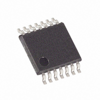
MAX5478EUD+ Maxim Integrated Products, MAX5478EUD+ Datasheet - Page 14

MAX5478EUD+
Manufacturer Part Number
MAX5478EUD+
Description
IC POT DGTL DUAL 256-TAP 14TSSOP
Manufacturer
Maxim Integrated Products
Datasheet
1.MAX5477ETE.pdf
(17 pages)
Specifications of MAX5478EUD+
Taps
256
Resistance (ohms)
50K
Number Of Circuits
2
Temperature Coefficient
35 ppm/°C Typical
Memory Type
Non-Volatile
Interface
I²C, 2-Wire Serial
Voltage - Supply
2.7 V ~ 5.25 V
Operating Temperature
-40°C ~ 85°C
Mounting Type
Surface Mount
Package / Case
14-TSSOP
Resistance In Ohms
50K
Number Of Pots
Dual
Taps Per Pot
256
Resistance
325 Ohms
Wiper Memory
Non Volatile
Digital Interface
Serial (2-Wire)
Operating Supply Voltage
2.7 V to 5.25 V
Supply Current
1 uA
Maximum Operating Temperature
+ 85 C
Minimum Operating Temperature
- 40 C
Description/function
Dual, 256 Tap, Nonvolatile, I2C, 50k Digital Potentiometer
Mounting Style
SMD/SMT
Supply Voltage (max)
5.25 V
Supply Voltage (min)
2.7 V
Tolerance
25 %
Lead Free Status / RoHS Status
Lead free / RoHS Compliant
VREGxNVREG: Data transfers from the volatile memory
register into the nonvolatile memory register.
The internal EEPROM consists of a 16-bit nonvolatile
register that retains the value written to it prior to power
down. The nonvolatile register is programmed with the
midscale value at the factory. The nonvolatile memory
is guaranteed for 50 years for wiper position retention
and up to 200,000 wiper write cycles. A write-protect
feature prevents accidental overwriting of the EEPROM.
Connect WP to V
protect feature. The wiper position only updates with
the value in the EEPROM when WP = V
to GND to allow EEPROM write cycles and to update
the wiper position from nonvolatile memory or directly
from the I
Upon power-up, the MAX5477/MAX5478/MAX5479
load the data stored in the nonvolatile memory register
into the volatile memory register, updating the wiper
position with the data stored in the nonvolatile memory
register. This initialization period takes 10µs.
The MAX5477/MAX5478/MAX5479 feature a low-power
standby mode. When the device is not being pro-
grammed, it enters into standby mode and supply cur-
rent drops to 500nA (typ).
The MAX5477/MAX5478/MAX5479 are ideal for circuits
requiring digitally controlled adjustable resistance,
such as LCD contrast control (where voltage biasing
adjusts the display contrast), or for programmable fil-
ters with adjustable gain and/or cutoff frequency.
Dual, 256-Tap, Nonvolatile, I
Digital Potentiometers
Figure 9. Positive LCD Bias Control Using a Voltage-Divider
14
______________________________________________________________________________________
MAX5477
MAX5478
MAX5479
2
C serial interface.
Applications Information
DD
5V
or leave open to enable the write-
H_
L_
W_
Nonvolatile Memory
MAX480
30V
DD
. Connect WP
Power-Up
Standby
V
OUT
Figures 9 and 10 show an application where the
MAX5477/MAX5478/MAX5479 provide an adjustable,
positive LCD bias voltage. The op amp provides buffer-
ing and gain to the resistor-divider network made by
the potentiometer (Figure 9) or by a fixed resistor and a
variable resistor (see Figure 10).
Figure
1st-order programmable application filter. Adjust the
gain of the filter with R
with R
gain (A) and the -3dB cutoff frequency (f
Connect the high and low terminals of one potentiome-
ter of a MAX5477 between the NULL inputs of a
MAX410 and the wiper to the op amp’s positive supply
to nullify the offset voltage over the operating tempera-
ture range. Install the other potentiometer in the feed-
back path to adjust the gain of the MAX410
Figure 13 shows the MAX5477/MAX5478/MAX5479
used as the feedback resistors in multiple adjustable
voltage reference applications. Independently adjust
the output voltages of the MAX6160 parts from 1.23V to
V
MAX5477/MAX5478/MAX5479.
Figure 10. Positive LCD Bias Control Using a Variable Resistor
IN
- 0.2V by changing the wiper positions of the
3
11 shows the MAX5477/MAX5478/MAX5479 in a
. Use the following equations to calculate the
2
Offset Voltage and Gain Adjustment
MAX5477
MAX5478
MAX5479
C-Interface,
Adjustable Voltage Reference
f
A
C
H_
L_
5V
=
=
Positive LCD Bias Control
1
2
2
, and set the cutoff frequency
π
W_
+
×
R
R
Programmable Filter
1
2
R
1
3
MAX480
×
30V
C
C
):
(Figure
V
OUT
12).


