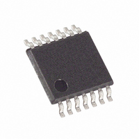
MAX5478EUD+ Maxim Integrated Products, MAX5478EUD+ Datasheet - Page 9

MAX5478EUD+
Manufacturer Part Number
MAX5478EUD+
Description
IC POT DGTL DUAL 256-TAP 14TSSOP
Manufacturer
Maxim Integrated Products
Datasheet
1.MAX5477ETE.pdf
(17 pages)
Specifications of MAX5478EUD+
Taps
256
Resistance (ohms)
50K
Number Of Circuits
2
Temperature Coefficient
35 ppm/°C Typical
Memory Type
Non-Volatile
Interface
I²C, 2-Wire Serial
Voltage - Supply
2.7 V ~ 5.25 V
Operating Temperature
-40°C ~ 85°C
Mounting Type
Surface Mount
Package / Case
14-TSSOP
Resistance In Ohms
50K
Number Of Pots
Dual
Taps Per Pot
256
Resistance
325 Ohms
Wiper Memory
Non Volatile
Digital Interface
Serial (2-Wire)
Operating Supply Voltage
2.7 V to 5.25 V
Supply Current
1 uA
Maximum Operating Temperature
+ 85 C
Minimum Operating Temperature
- 40 C
Description/function
Dual, 256 Tap, Nonvolatile, I2C, 50k Digital Potentiometer
Mounting Style
SMD/SMT
Supply Voltage (max)
5.25 V
Supply Voltage (min)
2.7 V
Tolerance
25 %
Lead Free Status / RoHS Status
Lead free / RoHS Compliant
Figure 1. I
TSSOP
10
11
12
13
14
—
—
1
2
3
4
5
6
7
8
9
SDA
SCL
2
PIN
C Serial-Interface Timing Diagram
t
HD:STA
THIN QFN
PARAMETERS ARE MEASURED FROM 30% TO 70%.
CONDITION
8, 16
15
14
13
12
11
10
EP
START
9
7
6
5
4
3
2
1
(S)
Dual, 256-Tap, Nonvolatile, I
_______________________________________________________________________________________
t
SU:DAT
NAME
GND
SDA
N.C.
t
SCL
V
LOW
WA
WB
WP
HA
HB
LA
LB
A2
A1
A0
EP
DD
t
R
Potentiometer A High Terminal
Potentiometer A Wiper Terminal
Potentiometer A Low Terminal
Potentiometer B High Terminal
Potentiometer B Wiper Terminal
Potentiometer B Low Terminal
Write-Protect Input. Connect to GND to allow changes to the wiper position and the data stored
in the EEPROM. Connect to V
EEPROM. See the Write Protect (WP) section for operating instructions.
Ground
Address Input 2. Connect to V
Address Input 1. Connect to V
Address Input 0. Connect to V
I 2 C Serial Data
I 2 C Clock Input
Power-Supply Input. Connect a +2.7V to +5.25V power supply to V
with a 0.1µF capacitor installed as close to the device as possible.
No Connection. Do not connect.
Exposed Paddle. Do not connect.
t
HIGH
t
F
t
HD:DAT
t
SU:STA
DD
REPEATED START
DD
DD
DD
CONDITION
or leave unconnected to enable the write protection of the
(SR)
or GND (see Table 1).
or GND (see Table 1).
or GND (see Table 1).
Digital Potentiometers
t
HD:STA
FUNCTION
ACKNOWLEDGE
(A)
t
SU:STO
2
C-Interface,
DD
CONDITION
Pin Description
STOP
and bypass V
(P)
t
BUF
CONDITION
START
(S)
DD
to GND
9


