DAC101S101QCMKX/NOPB National Semiconductor, DAC101S101QCMKX/NOPB Datasheet - Page 6
DAC101S101QCMKX/NOPB
Manufacturer Part Number
DAC101S101QCMKX/NOPB
Description
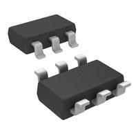
DAC RRO 10BIT MICROPWR TSOT23-6
Manufacturer
National Semiconductor
Series
PowerWise®r
Datasheet
1.DAC101S101CIMKNOPB.pdf
(20 pages)
Specifications of DAC101S101QCMKX/NOPB
Settling Time
8µs
Number Of Bits
10
Data Interface
Serial
Number Of Converters
1
Voltage Supply Source
Single Supply
Power Dissipation (max)
1.41mW
Operating Temperature
-40°C ~ 125°C
Mounting Type
Surface Mount
Package / Case
TSOT-23-6, TSOT-6
Lead Free Status / RoHS Status
Lead free / RoHS Compliant
Other names
DAC101S101QCMKX
Available stocks
Company
Part Number
Manufacturer
Quantity
Price


www.national.com
Specification Definitions
DIFFERENTIAL NON-LINEARITY (DNL) is the measure of
the maximum deviation from the ideal step size of 1 LSB,
which is V
DIGITAL FEEDTHROUGH is a measure of the energy inject-
ed into the analog output of the DAC from the digital inputs
when the DAC outputs are not updated. It is measured with a
full-scale code change on the data bus.
FULL-SCALE ERROR is the difference between the actual
output voltage with a full scale code (3FFh) loaded into the
DAC and the value of V
GAIN ERROR is the deviation from the ideal slope of the
transfer function. It can be calculated from Zero and Full-
Scale Errors as GE = FSE - ZE, where GE is Gain error, FSE
is Full-Scale Error and ZE is Zero Error.
GLITCH IMPULSE is the energy injected into the analog out-
put when the input code to the DAC register changes. It is
specified as the area of the glitch in nanovolt-seconds.
INTEGRAL NON-LINEARITY (INL) is a measure of the de-
viation of each individual code from a straight line through the
input to output transfer function. The deviation of any given
code from this straight line is measured from the center of that
code value. The end point method is used. INL for this product
is specified over a limited range, per the Electrical Tables.
LEAST SIGNIFICANT BIT (LSB) is the bit that has the small-
est value or weight of all bits in a word. This value is
REF
/ 1024 = V
A
A
x 1023 / 1024.
/ 1024.
6
where V
the DAC resolution in bits, which is 10 for the DAC101S101.
MAXIMUM LOAD CAPACITANCE is the maximum capaci-
tance that can be driven by the DAC with output stability
maintained.
MONOTONICITY is the condition of being monotonic, where
the DAC has an output that never decreases when the output
code increases.
MOST SIGNIFICANT BIT (MSB) is the bit that has the largest
value or weight of all bits in a word. Its value is 1/2 of V
POWER EFFICIENCY is the ratio of the output current to the
total supply current. The output current comes from the power
supply. The difference between the supply and output cur-
rents, is the power consumed by the device without a load.
SETTLING TIME is the time for the output to settle within 1/2
LSB of the final value.
WAKE-UP TIME is the time for the output to settle within 1/2
LSB of the final value after the device is commanded to the
active mode from any of the power down modes.
ZERO CODE ERROR is the output error, or voltage, present
at the DAC output after a code of 000h has been entered.
REF
is the supply voltage for this product, and "n" is
LSB = V
REF
/ 2
n
REF
.
Related parts for DAC101S101QCMKX/NOPB
Image
Part Number
Description
Manufacturer
Datasheet
Request
R

Part Number:
Description:
National Semiconductor [8-Bit D/A Converter]
Manufacturer:
National Semiconductor
Datasheet:
Part Number:
Description:
National Semiconductor [Media Coprocessor]
Manufacturer:
National Semiconductor
Datasheet:
Part Number:
Description:
Digitally Controlled Tone and Volume Circuit with Stereo Audio Power Amplifier, Microphone Preamp Stage and National 3D Sound
Manufacturer:
National Semiconductor
Datasheet:
Part Number:
Description:
Digitally Controlled Tone and Volume Circuit with Stereo Audio Power Amplifier, Microphone Preamp Stage and National 3D Sound
Manufacturer:
National Semiconductor
Datasheet:
Part Number:
Description:
AC97 Rev 2 Codec with Sample Rate Conversion and National 3D Sound
Manufacturer:
National Semiconductor
Part Number:
Description:
Manufacturer:
National Semiconductor
Datasheet:
Part Number:
Description:
Manufacturer:
National Semiconductor
Datasheet:
Part Number:
Description:
General Purpose, Low Voltage, Low Power, Rail-to-Rail Output Operational Amplifiers
Manufacturer:
National Semiconductor
Datasheet:
Part Number:
Description:
8-bit 20 MSPS flash A/D converter.
Manufacturer:
National Semiconductor
Datasheet:
Part Number:
Description:
Low Noise Quad Operational Amplifier
Manufacturer:
National Semiconductor
Datasheet:
Part Number:
Description:
Quad Differential Line Receivers
Manufacturer:
National Semiconductor
Datasheet:
Part Number:
Description:
Quad High Speed Trapezoidal? Bus Transceiver
Manufacturer:
National Semiconductor
Datasheet:
Part Number:
Description:
Dual Line Receiver
Manufacturer:
National Semiconductor
Datasheet:
Part Number:
Description:
TTL to 10k ECL Level Translator with Latch
Manufacturer:
National Semiconductor
Datasheet: