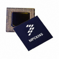
MPC8245TVV300D Freescale Semiconductor, MPC8245TVV300D Datasheet - Page 28

MPC8245TVV300D
Manufacturer Part Number
MPC8245TVV300D
Description
IC MPU 32BIT 300MHZ PPC 352-TBGA
Manufacturer
Freescale Semiconductor
Datasheet
1.MPC8245LZU266D.pdf
(68 pages)
Specifications of MPC8245TVV300D
Processor Type
MPC82xx PowerQUICC II 32-bit
Speed
300MHz
Voltage
1.8V
Mounting Type
Surface Mount
Package / Case
352-TBGA
Processor Series
MPC8xxx
Core
603e
Data Bus Width
32 bit
Maximum Clock Frequency
300 MHz
Operating Supply Voltage
1.8 V, 1.9 V, 2 V, 3.3 V
Maximum Operating Temperature
+ 105 C
Mounting Style
SMD/SMT
Minimum Operating Temperature
- 40 C
Lead Free Status / RoHS Status
Lead free / RoHS Compliant
Features
-
Lead Free Status / Rohs Status
Lead free / RoHS Compliant
Available stocks
Company
Part Number
Manufacturer
Quantity
Price
Company:
Part Number:
MPC8245TVV300D
Manufacturer:
Freescale Semiconductor
Quantity:
135
Company:
Part Number:
MPC8245TVV300D
Manufacturer:
Freescale Semiconductor
Quantity:
10 000
Part Number:
MPC8245TVV300D
Manufacturer:
FREESCALE
Quantity:
20 000
Electrical and Thermal Characteristics
Figure 17
4.7
Table 14
recommended operating conditions (see
28
Notes:
1. See the MPC8245 Integrated Processor Reference Manual for a description of the PIC interrupt control register (ICR) and
2. S_RST, S_FRAME, and S_INT shown in
3. The sys_logic_clk waveform is the clocking signal of the internal peripheral logic from the output of the peripheral logic PLL;
Num
1
2
3
4
5
6
7
S_CLK frequency programming.
and do not describe functional relationships between S_RST, S_FRAME, and S_INT. The MPC8245 Integrated Processor
Reference Manual describes the functional relationships between these signals.
sys_logic_clk is the same as SDRAM_SYNC_IN when the SDRAM_SYNC_OUT to SDRAM_SYNC_IN feedback loop is
implemented and the DLL is locked. See the MPC8245 Integrated Processor Reference Manual for a complete clocking
description.
SDA
SCL
S_CLK frequency
S_CLK duty cycle
S_CLK output valid time
Output hold time
S_FRAME, S_RST output valid time
S_INT input setup time to S_CLK
S_INT inputs invalid (hold time) to S_CLK
provides the PIC serial interrupt mode AC timing specifications for the MPC8245 at
PIC Serial Interrupt Mode AC Timing Specifications
shows the AC timing diagram for the I
S
t
I2CF
Characteristic
t
I2CL
t
I2SXKL
Table 14. PIC Serial Interrupt Mode AC Timing Specifications
MPC8245 Integrated Processor Hardware Specifications, Rev. 10
Figure 17. I
t
I2DXKL,
Figure 18
t
Table
I2DVKH
t
I2OVKL
1 sys_logic_clk period + 2
1/14 SDRAM_SYNC_IN
t
I2CH
2
C Bus AC Timing Diagram
and
2) with GV
t
2
I2SXKL
Figure
C bus.
Min
40
—
—
—
0
19, depict timing relationships to sys_logic_clk and S_CLK
Sr
DD
t
I2SVKH
= 3.3 V ± 5% and LV
t
I2KHKL
1 sys_logic_clk period + 6
1/2 SDRAM_SYNC_IN
t
Max
I2PVKH
60
—
—
6
0
t
I2CR
DD
Freescale Semiconductor
P
= 3.3 V ± 0.3 V.
t
I2CF
MHz
Unit
ns
ns
ns
ns
ns
%
S
Notes
—
—
—
1
2
2
2


