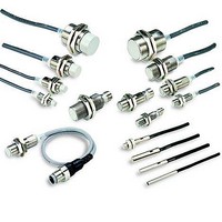
E2E2-X10MB1-M1 Omron, E2E2-X10MB1-M1 Datasheet - Page 15

E2E2-X10MB1-M1
Manufacturer Part Number
E2E2-X10MB1-M1
Description
Proximity Sensors With M12 Connector
Manufacturer
Omron
Type
Inductive Proximity Sensorr
Datasheet
1.E2E2-X2Y1-US.pdf
(20 pages)
Specifications of E2E2-X10MB1-M1
Maximum Operating Temperature
+ 70 C
Supply Voltage
24 V
Operating Supply Voltage
10 V to 55 V
Mounting Style
Panel
Sensing Distance
10 mm
Minimum Operating Temperature
- 25 C
Features
NO
Lead Free Status / Rohs Status
Lead free / RoHS Compliant
Turning OFF the Power
An output pulse may be generated when the power is turned OFF, so
design the system so that the load or load line power turns OFF first.
Influence of Surrounding Metal
The existence of a metal object other than the sensing object near the
sensing surface of the Proximity Sensor will affect detection perfor-
mance, increase the apparent operating distance, degrade tempera-
ture characteristics, and cause reset failures. For details, refer to the
influence of surrounding metal table in Safety Precautions for individ-
ual Sensors.
The values in the table are for the nuts provided with the Sensors.
Changing the nut material will change the influence of the surrounding
metal.
Power Transformers
Be sure to use an insulated transformer for a DC power supply. Do
not use an auto-transformer (single-coil transformer).
Precautions for AC 2-Wire/DC 2-Wire Sensors
Surge Protection
Although the Proximity Sensor has a surge absorption circuit, if there
is a device (motor, welder, etc.) that causes large surges near the
Proximity Sensor, insert a surge absorber near the source of the
surges.
Influence of Leakage Current
Even when the Proximity Sensor is OFF, a small amount of current
runs through the circuit as leakage current.
For this reason, a small current may remain in the load (residual
voltage in the load) and cause load reset failures. Verify that this
voltage is lower than the load reset voltage (the leakage current is
less than the load reset current) before using the Sensor.
Using an Electronic Device as the Load for an AC 2-Wire
Sensor
When using an electronic device, such as a Timer, some types of
devices use AC half-wave rectification. When a Proximity Sensor is
connected to a device using AC half-wave rectification, only AC half-
wave power will be supplied to the Sensor. This will cause the Sensor
operation to be unstable. Also, do not use a Proximity Sensor to turn
the power supply ON and OFF for electronic devices that use DC half-
wave rectification. In such a case, use a relay to turn the power supply
ON and OFF, and check the system for operating stability after
connecting it.
Examples of Timers that Use AC Half-wave Rectification
Timers: H3Y, H3YN, H3RN, H3CA-8, RD2P, and H3CR (-A, -A8, -AP,
-F, -G)
http://www.ia.omron.com/
Proximity Sensors Technical Guide
Countermeasures for Leakage Current (Examples)
AC 2-Wire Sensors
Connect a bleeder resistor to bypass the leakage current flowing in
the load so that the current flowing through the load is less than the
load reset current.
Calculate the bleeder resistance and allowable power using the
following equation.
R ≤
It is recommend that leeway be included in the actual values used.
For 100 VAC, use 10 kΩ or less and 3 W (5 W) or higher, and for 200
VAC, use 20 kΩ or less and 10 W (20 W) or higher. If the effects of
heat generation are a problem, use the number of watts in
parentheses ( ) or higher.
DC 2-Wire Sensors
Connect a bleeder resistor to bypass the leakage current flowing in
the load, and design the load current so that (leakage current) × (load
input impedance) < reset voltage.
Calculate the bleeder resistance and allowable power using the
following equation.
R ≤
It is recommend that leeway be included in the actual values used.
For 12 VDC, use 15 kΩ or less and 450 mW or higher, and for 24
VDC, use 30 kΩ or less and 0.1 W or higher.
P
I
P
i
i
R
OFF
When using an AC 2-Wire Sensor, connect a bleeder
resistor so that the Proximity Sensor current is at least 10
mA, and the residual load voltage when the Proximity
Sensor is OFF is less than the load reset voltage.
10 - I
i
R
Vs
: Watts of bleeder resistance (the actual number of watts
: Load current (mA)
: Watts of bleeder resistance (the actual number of watts
: Leakage current of Proximity Sensor (mA)
: Load reset current (mA)
(c)Copyright OMRON Corporation 2008 All Rights Reserved.
- i
Vs
used should be several times this number)
used should be several times this number)
OFFR
(kΩ)
(kΩ)
Bleeder resistor R
P >
Load
Bleeder resistor R
P >
Vs
R
Load
2
Vs
R
(mW)
2
(mW)
AC power supply
voltage Vs
Vs
C-4


