E2E2-X10MB1-M1 Omron, E2E2-X10MB1-M1 Datasheet - Page 8
E2E2-X10MB1-M1
Manufacturer Part Number
E2E2-X10MB1-M1
Description
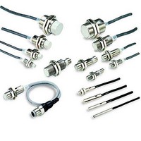
Proximity Sensors With M12 Connector
Manufacturer
Omron
Type
Inductive Proximity Sensorr
Datasheet
1.E2E2-X2Y1-US.pdf
(20 pages)
Specifications of E2E2-X10MB1-M1
Maximum Operating Temperature
+ 70 C
Supply Voltage
24 V
Operating Supply Voltage
10 V to 55 V
Mounting Style
Panel
Sensing Distance
10 mm
Minimum Operating Temperature
- 25 C
Features
NO
Lead Free Status / Rohs Status
Lead free / RoHS Compliant


I/O Circuit Diagrams
DC 2-Wire Models
DC 3-Wire Models
Operation
Operation
mode
mode
NO
NO
NC
NC
E2E2-X3D1
E2E2-X7D1
E2E2-X10D1
E2E2-X8MD1
E2E2-X14MD1
E2E2-X20MD1
E2E2-X3D2
E2E2-X7D2
E2E2-X10D2
E2E2-X8MD2
E2E2-X14MD2
E2E2-X20MD2
E2E2-X2C1
E2E2-X5C1
E2E2-X10C1
E2E2-X5MC1
E2E2-X10MC1
E2E2-X18MC1
E2E2-X2C2
E2E2-X5C2
E2E2-X10C2
E2E2-X5MC2
E2E2-X10MC2
E2E2-X18MC2
http://www.ia.omron.com/
Model
Model
(%)
(%)
Sensing
object
Sensing
object
Non-sensing
Non-sensing
area
area
Sensing object
Operation indicator
(red)
Control output
Sensing object
Operation indicator
(red)
Control output
Rated
sensing
distance
Rated
sensing
distance
Unstable
sensing
area
Timing Charts
100
100
Timing Charts
80
Not present
Not present
Set position
Stable sensing
Stable sensing
Present
Present
OFF
OFF
OFF
OFF
ON
ON
ON
ON
area
area
0
0
ON
OFF
ON
OFF
ON
OFF
ON
OFF
ON
OFF
Proximity Sensor
Proximity Sensor
(c)Copyright OMRON Corporation 2008 All Rights Reserved.
Setting indicator
(green)
Operation
indicator (red)
Control output
Operation
indicator (red)
Control output
Note: The load can be connected to either
Proximity
Sensor
main
circuit
Proximity
Sensor
main
circuit
the +V or 0 V side.
100 Ω
Output circuit
Output circuit
Brown
Black
Blue
Brown
Blue
Load
Load
E2E2
0 V
+V
0 V
+V
8
Related parts for E2E2-X10MB1-M1
Image
Part Number
Description
Manufacturer
Datasheet
Request
R

Part Number:
Description:
G6S-2GLow Signal Relay
Manufacturer:
Omron Corporation
Datasheet:
Part Number:
Description:
Compact, Low-cost, SSR Switching 5 to 20 A
Manufacturer:
Omron Corporation
Datasheet:
Part Number:
Description:
Manufacturer:
Omron Corporation
Datasheet:
Part Number:
Description:
Manufacturer:
Omron Corporation
Datasheet:
Part Number:
Description:
Manufacturer:
Omron Corporation
Datasheet:
Part Number:
Description:
Manufacturer:
Omron Corporation
Datasheet:
Part Number:
Description:
Manufacturer:
Omron Corporation
Datasheet:
Part Number:
Description:
Manufacturer:
Omron Corporation
Datasheet: