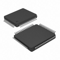
KSZ8873MLL Micrel Inc, KSZ8873MLL Datasheet - Page 35

KSZ8873MLL
Manufacturer Part Number
KSZ8873MLL
Description
IC ETHERNET SWITCH 3PORT 64-LQFP
Manufacturer
Micrel Inc
Specifications of KSZ8873MLL
Data Rate
100Mbps
Controller Type
Ethernet Switch Controller
Interface
MII
Voltage - Supply
1.8V, 2.5V, 3.3V
Operating Temperature
0°C ~ 70°C
Mounting Type
Surface Mount
Package / Case
64-LQFP
No. Of Ports
3
Ethernet Type
IEEE 802.3u
Supply Current
115mA
Supply Voltage Range
2.5V, 3.3V
Digital Ic Case Style
LQFP
No. Of Pins
64
Svhc
No SVHC (15-Dec-2010)
Base
RoHS Compliant
Number Of Primary Switch Ports
3
Internal Memory Buffer Size
32
Fiber Support
No
Integrated Led Drivers
Yes
Phy/transceiver Interface
MII
Power Supply Type
Analog/Digital
Data Rate (typ)
10/100Mbps
Vlan Support
Yes
Operating Temperature (max)
70C
Operating Temperature (min)
0C
Mounting
Surface Mount
Jtag Support
No
Operating Supply Voltage (max)
1.89/3.465V
Operating Temperature Classification
Commercial
Interface Type
MII, RMII
Operating Temperature Range
0°C To +70°C
Rohs Compliant
Yes
Lead Free Status / RoHS Status
Lead free / RoHS Compliant
Current - Supply
-
Lead Free Status / RoHS Status
Compliant, Lead free / RoHS Compliant
Other names
576-3459
Available stocks
Company
Part Number
Manufacturer
Quantity
Price
Company:
Part Number:
KSZ8873MLL
Manufacturer:
Micrel Inc
Quantity:
1 934
Company:
Part Number:
KSZ8873MLL
Manufacturer:
ADI
Quantity:
27
Company:
Part Number:
KSZ8873MLL AM
Manufacturer:
Micrel
Quantity:
1 638
Company:
Part Number:
KSZ8873MLLJ
Manufacturer:
Micrel
Quantity:
323
Micrel, Inc.
KSZ8873MLL/FLL/RLL
Rapid Spanning Tree Support
There are three operational states of the Discarding, Learning, and Forwarding assigned to each port for RSTP:
Discarding ports do not participate in the active topology and do not learn MAC addresses.
Discarding state: the state includs three states of the disable, blocking and listening of STP.
Port setting: "transmit enable = 0, receive enable = 0, learning disable = 1."
Software action: the processor should not send any packets to the port. The switch may still send specific packets to the
processor (packets that match some entries in the static table with “overriding bit” set) and the processor should discard
those packets. When disable the port’s learning capability (learning disable=’1’), set the register 2 bit 5 and bit 4 will flush
rapidly the port related entries in the dynamic MAC table and static MAC table.
Note: processor is connected to port 3 via MII interface. Address learning is disabled on the port in this state.
Ports in Learning states learn MAC addresses, but do not forward user traffic.
Learning state: only packets to and from the processor are forwarded. Learning is enabled.
Port setting: “transmit enable = 0, receive enable = 0, learning disable = 0.”
Software action: The processor should program the static MAC table with the entries that it needs to receive (e.g., BPDU
packets). The “overriding” bit should be set so that the switch will forward those specific packets to the processor. The
processor may send packets to the port(s) in this state, see “Tail Tagging Mode” section for details. Address learning is
enabled on the port in this state.
Ports in Forwarding states fully participate in both data forwarding and MAC learning.
Forwarding state: packets are forwarded and received normally. Learning is enabled.
Port setting: “transmit enable = 1, receive enable = 1, learning disable = 0.”
Software action: The processor should program the static MAC table with the entries that it needs to receive (e.g., BPDU
packets). The “overriding” bit should be set so that the switch will forward those specific packets to the processor. The
processor may send packets to the port(s) in this state, see “Tail Tagging Mode” section for details. Address learning is
enabled on the port in this state.
RSTP uses only one type of BPDU called RSTP BPDUs. They are similar to STP Configuration BPDUs with the exception
of a type field set to “version 2” for RSTP and “version 0” for STP, and a flag field carrying additional information.
Tail Tagging Mode
The Tail Tag is only seen and used by the port 3 interface, which should be connected to a processor. It is an effective
way to retrieve the ingress port information for spanning tree protocol IGMP snooping and other applications. The Bit 1
and bit 0 in the one byte tail tagging is used to indicate the source/destination port in port 3. Bit 3 and bit 2 are used for the
priority setting of the ingress frame in port 3. Other bits are not used. The Tail Tag feature is enable by setting register 3
bit 6.
Figure 7. Tail Tag Frame Format
September 2010
35
M9999-092309-1.2


