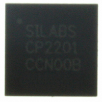
CP2201-GM Silicon Laboratories Inc, CP2201-GM Datasheet - Page 91

CP2201-GM
Manufacturer Part Number
CP2201-GM
Description
IC ETH CTRLR SNGL-CHIP 28QFN
Manufacturer
Silicon Laboratories Inc
Specifications of CP2201-GM
Package / Case
48-TQFP, 48-VQFP
Controller Type
Ethernet Controller, MAC/10Base-T
Interface
Parallel/Serial
Voltage - Supply
3.1 V ~ 3.6 V
Current - Supply
75mA
Operating Temperature
-40°C ~ 85°C
Mounting Type
Surface Mount
Ethernet Connection Type
1000BASE-T or 100BASE-T or 10BASE-T
Minimum Operating Temperature
- 40 C
Mounting Style
SMD/SMT
Product
Ethernet Controllers
Standard Supported
IEEE 802.3
Data Rate
10 Mbps or 100 Mbps or 1000 Mbps
Maximum Operating Temperature
+ 85 C
No. Of Ports
1
Ethernet Type
IEEE 802.3
Interface Type
Parallel
Supply Current
60mA
Supply Voltage Range
3.1V To 3.6V
Operating Temperature Range
-40°C To +85°C
Rohs Compliant
Yes
Lead Free Status / RoHS Status
Lead free / RoHS Compliant
For Use With
336-1326 - KIT REF DESIGN PWR OVER ETHERNET336-1316 - KIT EVAL FOR CP2201 ETH CTRLR
Lead Free Status / Rohs Status
Lead free / RoHS Compliant
Other names
336-1313
Available stocks
Company
Part Number
Manufacturer
Quantity
Price
Company:
Part Number:
CP2201-GM
Manufacturer:
SiliconL
Quantity:
48
Part Number:
CP2201-GMR
Manufacturer:
SILICON LABS/芯科
Quantity:
20 000
Important Note: When using auto-negotiation, the auto-negotiation enable bit, AUTONEG (PHYCF.4), must
Bit 7:
Bit 6:
Bit 5:
Bit 4:
Bit 3:
Bit 2:
Bit 1:
Bit 0:
PHYEN
R/W
Bit7
PHYEN: Physical Layer Enable
0: The physical layer is placed in a low-power state with limited functionality.
1: The physical layer is placed in a normal power state and is fully functional.
TXEN: Transmitter Enable
0: Physical Layer’s transmitter is placed in a low-power state. Packet transmission and Link Pulse
Generation Functions are disabled.
1. Physical layer’s transmitter is enabled.
RXEN: Receiver Enable
0: Physical layer’s receiver is placed in a low-power state. Packet reception is disabled.
1: Physical layer’s receiver is enabled.
DPLXMD: Full-duplex Mode Enable Bit
Note: This bit is read-only when Auto-Negotiation is enabled.
0: Half-duplex mode is selected.
1: Full-duplex mode is selected.
LBMD: Loopback Mode Enable Bit
Note: Loopback mode is automatically disabled if a jabber condition is detected.
0: Loopback mode is disabled.
1: Loopback mode is enabled.
LPRFAULT: Link Partner Remote Fault (Local Fault) Indicator
0: Normal operation.
1: The link partner has detected a link fault and has sent notification during auto-negotiation. This
condition can occur if the local transmitter is disabled and link pulses are no longer generated.
POLREV: Polarity Reversed Indicator
0: Incorrect link polarity has not been detected.
1: Incorrect link polarity detected. Link polarity has been automatically reversed.
LINKSTA: Link Status Indicator
0: Link is bad.
1: Link is good.
TXEN
R/W
be set to “1” prior to
clear one of the three enable bits (PHYEN, TXEN, and RXEN) to “0” then set it back to “1”.
Bit6
Register 70. PHYCN: Physical Layer Control Register
RXEN
R/W
Bit5
setting PHYEN, TXEN, and RXEN to 1. To restart auto-negotiation,
DPLXMD
R/W or RO
Bit4
LBMD
Rev. 1.0
R/W
Bit3
LPRFAULT POLREV
Bit2
R
Bit1
R
LINKSTA
Bit0
CP2200/1
R
00000000
Reset Value
Address:
0x78
91


