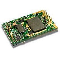
PKM4119CPINB Ericsson Power Modules, PKM4119CPINB Datasheet - Page 16

PKM4119CPINB
Manufacturer Part Number
PKM4119CPINB
Description
DC/DC Converters & Regulators 2.5 Vdc 55A Iso Input 36-75V 137.5W
Manufacturer
Ericsson Power Modules
Series
PKM-Cr
Datasheet
1.PKM4213CPINBSP.pdf
(23 pages)
Specifications of PKM4119CPINB
Product
Isolated
Output Power
30 W
Input Voltage Range
36 V to 75 V
Number Of Outputs
1
Output Voltage (channel 1)
1.5 V
Output Current (channel 1)
20 A
Isolation Voltage
1.5 KV
Package / Case Size
Quarter Brick
Output Type
Isolated
Lead Free Status / Rohs Status
Lead free / RoHS Compliant
Operating information continued
Parallel Operation
The PKM 4000CSeries DC/DC converters can be paralleled
for redundancy if external o-ring diodes are used in series
with the outputs. It is not recommended to parallel the PKM
4000C Series DC/DC converters for increased power without
using external current sharing circuits.
See Design Note 006 for detailed information.
Remote Sense
All PKM 4000CSeries DC/DC converters have remote sense
that can be used to compensate for moderate amounts of
resistance in the distribution system and allow for voltage
regulation at the load or other selected point. The remote
sense lines will carry very little current and do not need a
large cross sectional area. However, the sense lines on the
Pcb should be located close to a ground trace or ground
plane. In a discrete wiring situation, the use of twisted pair
wires or other technique to reduce noise susceptibility is
highly recommended. The remote sense circuitry will
compensate for up to 10% voltage drop between the sense
voltage and the voltage at the output pins. The output voltage
and the remote sense voltage offset must be less than the
minimum over voltage trip point. If the remote sense is not
needed the —Sense should be connected to —Out and +Sense
should be connected to +Out.
Over Temperature Protection (OTP)
The PKM 4000CSeries DC/DC converters are protected from
thermal overload by an internal over temperature shutdown
circuit. When the Pcb temperature (TC reference point)
exceeds the temperature trig point (~120 °C) the OTP circuit
will cut down output power. The converter will stop until safe
operating temperature is restored. Hysteresis between OTP
trig point and restart is approx 10°C. Time between OTP and
restart is dependant on cooling of DC/DC converter.
Over Voltage Protection (OVP)
The PKM 4000CSeries DC/DC converters have output
overvoltage protection. In the event of an output overvoltage
condition, the converter will shut down immediately. The
converter make continous attempts to start up (non-latching
mode) and resume normal operation automatically.
Over Current Protection (OCP)
The PKM 4000CSeries DC/DC converters include current
limiting circuitry that allows them to withstand continuous
overloads or short circuit conditions on the output. The
output voltage will decrease towards zero for output currents
in excess of max output current (Iomax).
The converter will resume normal operation after removal of
the overload. The load distribution system should be
designed to carry the maximum output short circuit current
specified.
ESKEVIN
Approved
SEC/D (Julia You)
PKM 4000C PINB series Direct Converters
Input 36-75 V, Output 55 A/204 W
Checked
EYINGJI
Thermal Consideration
General
The PKM 4000Cseries DC/DC converters are designed to
operate in a variety of thermal environments, however
sufficient cooling should be provided to help ensure reliable
operation. Heat is removed by conduction, convection and
radiation to the surrounding environment. Increased airflow
enhances the heat transfer via convection. The available load
current vs. ambient air temperature and airflow at Vin =53 V
for each model is according to the information given under the
output section. The test is done in a wind tunnel with a cross
section of 305 x 305 mm, the DC/DC converter vertically
mounted on a 16 layer Pcb with a size of 254 x 254 mm, each
layer with 35 μm (1 oz) copper. Proper cooling can be verified
by measuring the temperature of selected devices. Peak
temperature can occur at positions P1 - P4. The temperature
at these positions should not exceed the recommended max
values.
Note that the max value is the absolute maximum rating
(non destruction) and that the electrical Output data is
guaranteed up to T
See Design Note 019 for further information.
3/1301-BMR 637 01 Uen
Date
2007-12-10
Position
P
P
P
P
1
2
3
4
Device
Pcb
Mosfet
Mosfet
Transformer
Technical Specifi cation
EN/LZT 146 307 R4B August 2009
© Ericsson Power Modules AB
Rev
C
ref
+90°C.
Designation
T
Tsurface
Tsurface
Tsurface
ref
Reference
max value
110º C
120º C
120º C
130º C
16


