PKM4119CPINB Ericsson Power Modules, PKM4119CPINB Datasheet - Page 2
PKM4119CPINB
Manufacturer Part Number
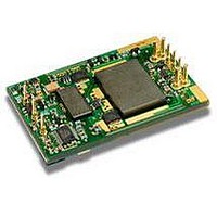
PKM4119CPINB
Description
DC/DC Converters & Regulators 2.5 Vdc 55A Iso Input 36-75V 137.5W
Manufacturer
Ericsson Power Modules
Series
PKM-Cr
Datasheet
1.PKM4213CPINBSP.pdf
(23 pages)
Specifications of PKM4119CPINB
Product
Isolated
Output Power
30 W
Input Voltage Range
36 V to 75 V
Number Of Outputs
1
Output Voltage (channel 1)
1.5 V
Output Current (channel 1)
20 A
Isolation Voltage
1.5 KV
Package / Case Size
Quarter Brick
Output Type
Isolated
Lead Free Status / Rohs Status
Lead free / RoHS Compliant


Prepared (also subject responsible if other)
SEC/D Kevin Zhou
Approved
SEC/D Kevin Zhou
PKM 4000C PINB series Direct Converters
Input 36-75 V, Output 55 A/204 W
General Information
Ordering Information
See Contents for individual product ordering numbers.
Option
Baseplate
Single Pin*
Positive Remote Control Logic
Increased stand-off height
Lead length 3.69 mm (0.145 in)
Lead length 4.57 mm (0.180 in)
Note: As an example a positive logic, increased standoff, short pin product
would be PKM 4110C PIPNBMLA.
*Single Pin option only for current less than 50A.
Reliability
The Mean Time Between Failure (MTBF) is calculated at full
output power and an operating ambient temperature (T
+40°C, which is a typical condition in Information and
Communication Technology (ICT) equipment. Different
methods could be used to calculate the predicted MTBF
and failure rate which may give different results. Ericsson
Power Modules currently uses two different methods,
Ericsson failure rate data system DependTool and
Telcordia SR332.
Predicted MTBF for the series is:
-
-
The Ericsson failure rate data system is based on field
tracking data. The data corresponds to actual failure rates
of components used in ICT equipment in temperature
controlled environments (T
Telcordia SR332 is a commonly used standard method
intended for reliability calculations in ICT equipment. The
parts count procedure used in this method was originally
modelled on the methods from MIL-HDBK-217F, Reliability
Predictions of Electronic Equipment. It assumes that no
reliability data is available on the actual units and devices
for which the predictions are to be made, i.e. all predictions
are based on generic reliability parameters.
Compatibility with RoHS requirements
The products are compatible with the relevant clauses and
requirements of the RoHS directive 2002/95/EC and have a
maximum concentration value of 0.1% by weight in
homogeneous materials for lead, mercury, hexavalent
chromium, PBB and PBDE and of 0.01% by weight in
homogeneous materials for cadmium.
Exemptions in the RoHS directive utilized in Ericsson
Power Modules products include:
-
2.7 million hours according to DependTool.
1.4 million hours according to Telcordia SR332, issue
1, Black box technique.
Lead in high melting temperature type solder (used to
solder the die in semiconductor packages)
A
= -5...+65°C).
Suffix
SP
P
M
LA
LB
Ordering No.
PKM 4110C PI
PKM 4211C PINBSP
PKM 4110C PIPNB
PKM 4110C PINBM
PKM 4110C PINBLA
PKM 4110C PINBLB
Checked
MICOSPE
A
) of
PRODUCT SPECIFICATION
No.
1/1301-BMR63701
Date
2007-1-29
-
-
Quality Statement
The products are designed and manufactured in an
industrial environment where quality systems and methods
like ISO 9000, 6σ (sigma), and SPC are intensively in use to
boost the continuous improvements strategy. Infant
mortality or early failures in the products are screened out
and they are subjected to an ATE-based final test.
Conservative design rules, design reviews and product
qualifications, plus the high competence of an engaged
work force, contribute to the high quality of our products.
Warranty
Warranty period and conditions are defined in Ericsson
Power Modules General Terms and Conditions of Sale.
Limitation of Liability
Ericsson power Modules does not make any other
warranties, expressed or implied including any warranty of
merchantability or fitness for a particular purpose
(including, but not limited to, use in life support
applications, where malfunctions of product can cause
injury to a person’s health or life).
Lead in glass of electronics components and in
electronic ceramic parts (e.g. fill material in chip
resistors)
Lead as an alloying element in copper alloy containing
up to 4% lead by weight (used in connection pins
made of Brass)
Technical Specifi cation
EN/LZT 146 307 R4B August 2009
© Ericsson Power Modules AB
Rev
F
Reference
2 (3)
2
Related parts for PKM4119CPINB
Image
Part Number
Description
Manufacturer
Datasheet
Request
R

Part Number:
Description:
37.5-150W DC/DC POWER MODULES
Manufacturer:
Ericsson Power Modules
Part Number:
Description:
DC/DC Power Supply Dual-OUT 3.3V/5V 9.6A/6.4A 40W 10-Pin
Manufacturer:
Ericsson Power Modules
Part Number:
Description:
DC/DC Power Supply Single-OUT 3.3V 20A 66W 8-Pin Quarter-Brick
Manufacturer:
Ericsson Power Modules
Datasheet:
Part Number:
Description:
DC/DC Power Supply Single-OUT 1.8V 50A 90W 11-Pin
Manufacturer:
Ericsson Power Modules
Part Number:
Description:
Module DC-DC 1-OUT 1.8V 30A 54W 9-Pin
Manufacturer:
Ericsson Power Modules

Part Number:
Description:
Module DC-DC 1-OUT 1.8V 60A 108W 11-Pin Half-Brick
Manufacturer:
Ericsson Power Modules
Datasheet:

Part Number:
Description:
Module DC-DC 1-OUT 12V 25A 300W 11-Pin Half-Brick
Manufacturer:
Ericsson Power Modules
Part Number:
Description:
Module DC-DC 1-OUT 5V 20A 100W Quarter-Brick
Manufacturer:
Ericsson Power Modules

Part Number:
Description:
Module DC-DC 1-OUT 12V 6A 72W 8-Pin 1/8-Brick
Manufacturer:
Ericsson Power Modules
Datasheet:
Part Number:
Description:
Module DC-DC 1-OUT 5.05V 2A 10W 18-Pin SMD
Manufacturer:
Ericsson Power Modules
Part Number:
Description:
Manufacturer:
Ericsson Power Modules
Datasheet:

Part Number:
Description:
Module DC-DC 1-OUT 5V 60A 300W 11-Pin Half-Brick Tray
Manufacturer:
Ericsson Power Modules
Part Number:
Description:
Module DC-DC 1-OUT 12V 1A 12W 18-Pin
Manufacturer:
Ericsson Power Modules
Datasheet:
Part Number:
Description:
Module DC-DC 2-OUT 12V/-12V 0.25A 6W 18-Pin SMD
Manufacturer:
Ericsson Power Modules
Part Number:
Description:
Module DC-DC 1-OUT 28V 11A 310W 11-Pin Half-Brick Tray
Manufacturer:
Ericsson Power Modules
Datasheet: