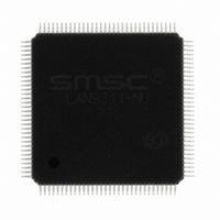
LAN9311-NU SMSC, LAN9311-NU Datasheet - Page 37

LAN9311-NU
Manufacturer Part Number
LAN9311-NU
Description
IC ETHER SW 2PRT 16BIT 128-VTQFP
Manufacturer
SMSC
Type
Two Port Managed Ethernet Switchr
Specifications of LAN9311-NU
Controller Type
Ethernet Switch Controller
Interface
Serial EEPROM
Voltage - Supply
3.3V
Operating Temperature
0°C ~ 70°C
Mounting Type
Surface Mount
Package / Case
128-TQFP, 128-VQFP
Product
Ethernet Switches
Number Of Transceivers
1
Standard Supported
802.3, 802.3u
Data Rate
10 MB, 100 MB
Supply Voltage (max)
3.3 V
Supply Voltage (min)
0 V
Maximum Operating Temperature
+ 70 C
Ethernet Connection Type
10 Base-T, 100 Base-TX
Minimum Operating Temperature
0 C
Mounting Style
SMD/SMT
For Use With
638-1076 - EVALUATION BOARD LAN9311-NU
Lead Free Status / RoHS Status
Lead free / RoHS Compliant
Current - Supply
-
Lead Free Status / Rohs Status
Lead free / RoHS Compliant
Other names
638-1075
Available stocks
Company
Part Number
Manufacturer
Quantity
Price
Company:
Part Number:
LAN9311-NU
Manufacturer:
CINCERA
Quantity:
3 023
Company:
Part Number:
LAN9311-NU
Manufacturer:
Microchip Technology
Quantity:
10 000
Part Number:
LAN9311-NU
Manufacturer:
SMSC
Quantity:
20 000
- Current page: 37 of 460
- Download datasheet (5Mb)
Two Port 10/100 Managed Ethernet Switch with 16-Bit Non-PCI CPU Interface
Datasheet
SMSC LAN9311/LAN9311i
4.2.1
RESET SOURCE
Digital Reset
Virtual PHY
Port 2 PHY
Port 1 PHY
Soft Reset
nRST Pin
Note 4.1
Chip-Level Resets
A chip-level reset event activates all internal resets, effectively resetting the entire LAN9311/LAN9311i.
Configuration straps are latched, and the EEPROM Loader is run as a result of chip-level resets. A
chip-level reset is initiated by assertion of any of the following input events:
Chip-level reset completion/configuration can be determined by polling the READY bit of the
Configuration Register (HW_CFG)
When set, the READY bit indicates that the reset has completed and the device is ready to be
accessed.
With the exception of the
Register
(RESET_CTL), read access to any internal resources is forbidden while the READY bit is cleared.
Writes to any address are invalid until the READY bit is set.
Note: The LAN9311/LAN9311i must be read at least once after any chip-level reset to ensure that
POR
Power-On Reset (POR)
nRST Pin Reset
write operations function properly.
Table 4.1 Reset Sources and Affected LAN9311/LAN9311i Circuitry
(PMT_CTRL),
In the case of a soft reset, the EEPROM Loader is run, but loads only the MAC address
into the Host MAC. No other values are loaded by the EEPROM Loader in this case.
X
X
X
X
X
X
Byte Order Test Register
Hardware Configuration Register
X
X
X
or
DATASHEET
X
X
X
X
X
Power Management Control Register (PMT_CTRL)
37
X
X
X
X
X
X
X
X
(BYTE_TEST), and
(HW_CFG),
X
X
X
X
X
X
Power Management Control
Reset Control Register
X
X
X
Revision 1.7 (06-29-10)
X
X
until it is set.
Note 4.1
Hardware
X
X
X
Related parts for LAN9311-NU
Image
Part Number
Description
Manufacturer
Datasheet
Request
R

Part Number:
Description:
Ethernet ICs Two Port 10/100 Ethernet Switch
Manufacturer:
SMSC
Datasheet:

Part Number:
Description:
FAST ETHERNET PHYSICAL LAYER DEVICE
Manufacturer:
SMSC Corporation
Datasheet:

Part Number:
Description:
357-036-542-201 CARDEDGE 36POS DL .156 BLK LOPRO
Manufacturer:
SMSC Corporation
Datasheet:

Part Number:
Description:
357-036-542-201 CARDEDGE 36POS DL .156 BLK LOPRO
Manufacturer:
SMSC Corporation
Datasheet:

Part Number:
Description:
357-036-542-201 CARDEDGE 36POS DL .156 BLK LOPRO
Manufacturer:
SMSC Corporation
Datasheet:

Part Number:
Description:
4-PORT USB2.0 HUB CONTROLLER
Manufacturer:
SMSC Corporation
Datasheet:

Part Number:
Description:
Manufacturer:
SMSC Corporation
Datasheet:

Part Number:
Description:
Manufacturer:
SMSC Corporation
Datasheet:

Part Number:
Description:
FDC37C672ENHANCED SUPER I/O CONTROLLER WITH FAST IR
Manufacturer:
SMSC Corporation
Datasheet:

Part Number:
Description:
COM90C66LJPARCNET Controller/Transceiver with AT Interface and On-Chip RAM
Manufacturer:
SMSC Corporation
Datasheet:

Part Number:
Description:
Manufacturer:
SMSC Corporation
Datasheet:

Part Number:
Description:
Manufacturer:
SMSC Corporation
Datasheet:

Part Number:
Description:
Manufacturer:
SMSC Corporation
Datasheet:

Part Number:
Description:
Manufacturer:
SMSC Corporation
Datasheet:


