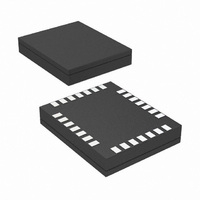
USBN9603SLBX National Semiconductor, USBN9603SLBX Datasheet - Page 24

USBN9603SLBX
Manufacturer Part Number
USBN9603SLBX
Description
IC CTRLR FULL SPEED 28-LAMCSP
Manufacturer
National Semiconductor
Datasheet
1.USBN9604-28MNOPB.pdf
(60 pages)
Specifications of USBN9603SLBX
Controller Type
USB 2.0 Controller
Interface
Parallel/Serial
Voltage - Supply
3 V ~ 5.5 V
Current - Supply
30mA
Operating Temperature
0°C ~ 70°C
Mounting Type
Surface Mount
Package / Case
28-Laminate CSP
For Use With
USBN9604-HS-EB - KIT NODE CONTROLLER SAMPLE
Lead Free Status / RoHS Status
Lead free / RoHS Compliant
Other names
USBN9603SLBX
USBN9603SLBX/NOPB
USBN9603SLBXTR
USBN9603SLBX/NOPB
USBN9603SLBXTR
Available stocks
Company
Part Number
Manufacturer
Quantity
Price
www.national.com
6.0 Functional Description
6.2 ENDPOINT OPERATION
6.2.1
Packets are broadcast from the host controller to all the nodes on the USB network. Address detection is implemented in
hardware to allow selective reception of packets and to permit optimal use of microcontroller bandwidth. One function ad-
dress with seven different endpoint combinations is decoded in parallel. If a match is found, then that particular packet is
received into the FIFO; otherwise it is ignored.
The incoming USB Packet Address field and Endpoint field are extracted from the incoming bitstream. Then the address
field is compared to the Function Address register (FADR). If a match is detected, the Endpoint field is compared to all of
the Endpoint Control registers (EPCx) in parallel. A match then causes the payload data to be received or transmitted using
the respective endpoint FIFO.
6.2.2
The device uses a total of seven transmit and receive FIFOs: one bidirectional transmit and receive FIFO for the mandatory
control endpoint, three transmit FIFOs and three receive FIFOs. As shown in Table 4, the bidirectional FIFO for the control
endpoint is 8 bytes deep. The additional unidirectional FIFOs are 64 bytes each for both transmit and receive. Each FIFO
can be programmed for one exclusive USB endpoint, used together with one globally decoded USB function address. The
firmware must not enable both transmit and receive FIFOs for endpoint zero at any given time.
Address Detection
Transmit and Receive Endpoint FIFOs
match
FADR Register
ADDR Field
Figure 19. USB Function Address/Endpoint Decoding
(Continued)
EPC0 Register
EPC1 Register
EPC2 Register
EPC3 Register
EPC4 Register
EPC5 Register
EPC6 Register
Endpoint Field
24
match
- USB Packet -
Receive/Transmit FIFO0
Transmit FIFO1
Receive FIFO1
Transmit FIFO2
Receive FIFO2
Transmit FIFO3
Receive FIFO3


