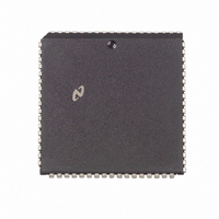
DP8390DV National Semiconductor, DP8390DV Datasheet - Page 13

DP8390DV
Manufacturer Part Number
DP8390DV
Description
IC CTRLR NETWORK IN (NIC)68PLCC
Manufacturer
National Semiconductor
Datasheet
1.DP8390DN.pdf
(56 pages)
Specifications of DP8390DV
Controller Type
Network Interface Controller (NIC)
Voltage - Supply
5V
Current - Supply
40mA
Mounting Type
Surface Mount
Package / Case
68-LCC (J-Lead)
Lead Free Status / RoHS Status
Contains lead / RoHS non-compliant
Operating Temperature
-
Interface
-
Other names
*DP8390DV
Available stocks
Company
Part Number
Manufacturer
Quantity
Price
Company:
Part Number:
DP8390DV
Manufacturer:
NSC
Quantity:
5 510
Company:
Part Number:
DP8390DV
Manufacturer:
SIEMENS
Quantity:
5 510
Part Number:
DP8390DV
Manufacturer:
NS/国半
Quantity:
20 000
Company:
Part Number:
DP8390DV NS32490DV
Manufacturer:
NSC
Quantity:
5 510
Company:
Part Number:
DP8390DV NS32490DV
Manufacturer:
SUPERTEX
Quantity:
5 510
Company:
Part Number:
DP8390DV/NS32490DV
Manufacturer:
NSC
Quantity:
5 510
9 0 Remote DMA
REMOTE WRITE
A Remote Write transfer is used to move a block of data
from the host into local buffer memory The Remote DMA
will read data from the I O port and sequentially write it to
local buffer memory beginning at the Remote Start Address
The DMA Address will be incremented and the Byte Coun-
ter will be decremented after each transfer The DMA is
terminated when the Remote Byte Count Register reaches
a count of zero
REMOTE READ
A Remote Read transfer is used to move a block of data
from local buffer memory to the host The Remote DMA will
sequentially read data from the local buffer memory begin-
ning at the Remote Start Address and write data to the I O
port The DMA Address will be incremented and the Byte
Counter will be decremented after each transfer The DMA
is terminated when the Remote Byte Count Register reach-
es zero
REMOTE DMA WRITE
Setting PRQ Using the Remote Read
Under certain conditions the NIC’s bus state machine may
issue MWR and PRD before PRQ for the first DMA trans-
fer of a Remote Write Command If this occurs this could
cause data corruption or cause the remote DMA count to
be different from the main CPU count causing the system to
‘‘lock up’’
To prevent this condition when implementing a Remote
DMA Write the Remote DMA Write command should first
be preceded by a Remote DMA Read command to insure
that the PRQ signal is asserted before the NIC starts its port
read cycle The reason for this is that the state machine that
asserts PRQ runs independently of the state machine that
controls the DMA signals The DMA machine assumes that
PRQ is asserted but actually may not be To remedy this
situation a single Remote Read cycle should be inserted
before the actual DMA Write Command is given This will
ensure that PRQ is asserted when the Remote DMA Write is
subsequently executed This single Remote Read cycle is
Note The dashed lines indicate incorrect timing
(Continued)
Timing Diagram for Dummy Remote Read
13
called a ‘‘dummy Remote Read ’’ In order for the dummy
Remote Read cycle to operate correctly the Start Address
should be programmed to a known safe location in the buff-
er memory space and the Remote Byte Count should be
progammed to a value greater than 1 This will ensure that
the master read cycle is performed safely eliminating the
possiblity of data corruption
Remote Write with High Speed Buses
When implementing the Remote DMA Write solution in pre-
vious section with high speed buses and CPU’s timing
problems may cause the system to hang Therefore addi-
tional considerations are required
The problem occurs when the system can execute the dum-
my Remote Read and then start the Remote Write before
the NIC has had a chance to execute the Remote Read If
this happens the PRQ signal will not get set and the Re-
mote Byte Count and Remote Start Address for the Remote
Write operation could be corrupted This is shown by the
hatched waveforms in the timing diagram below The execu-
tion of the Remote Read can be delayed by the local DMA
operations (particularly during end-of-packet processing)
To ensure the dummy Remote Read does execute a delay
must be inserted between writing the Remote Read Com-
mand and starting to write the Remote Write Start Address
(This time is designated in figure below by the delay arrows )
The recommended method to avoid this problem is after
the Remote Read command is given to poll both bytes of
the Current Remote DMA Address Registers When the ad-
dress has incremented PRQ has been set Software should
recognize this and then start the Remote Write
An additional caution for high speed systems is that the
polling must follow guidelines specified at the end of Sec-
tion 13 That is there must be at least 4 bus clocks between
chip selects (For example when BSCK
this time should be 200 ns )
The general flow for executing a Remote Write is
1 Set Remote Byte Count to a value
Address to unused RAM (one location before the transmit
start address is usually a safe location)
l
1 and Remote Start
e
20 MHz then
TL F 8582 – 96


