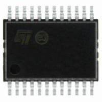
STPIC44L02PTR STMicroelectronics, STPIC44L02PTR Datasheet

STPIC44L02PTR
Specifications of STPIC44L02PTR
Related parts for STPIC44L02PTR
STPIC44L02PTR Summary of contents
Page 1
SERIAL-IN PARALLEL-IN LOW SIDE PRE-FET DRIVER DEVICES ARE CASCADABLE INTERNAL 55V INDUCTIVE LOAD CLAMP AND VGS PROTECTION CLAMP FOR EXTERNAL POWER FETS INDEPENDENT SHORTED-LOAD AND SHORT-TO-BATTERY FAULT DETECTION ON ALL GATE TERMINALS INDEPENDENT OFF-STATE OPEN-LOAD FAULT SENSE OVER-BATTERY-VOLTAGE LOCKOUT ...
Page 2
... Shorted load fault conditions must be present for at least the shorted load deglicth time, ORDERING CODES Type STPIC44L02PTR 2/ flagged as a fault. A fault flag is (STBDG) sent to the control device as well as the serial fault register bits ...
Page 3
Figure 1 : Schematic Diagram STPIC44L02 3/21 ...
Page 4
STPIC44L02 PIN DESCRIPTION PIN No SYMBOL I/O 1 FLT I Fault Flag. FLT is a logic level open-drain output that provides a real time fault flag for shorted-load, open-load, over-battery voltage, under-battery voltage faults. The device can be ORed with ...
Page 5
Figure 2 : Pin Configuration ABSOLUTE MAXIMUM RATINGS Symbol V Logic Supply Voltage (See Note Battery Supply Voltage BAT V Logic Input Voltage Range I V Output Voltage (SDO and FLT Output Voltage O V ...
Page 6
STPIC44L02 ELECTRICAL CHARACTERISTICS OVER RECOMMENDED OPERATING FREE-AIR TEMPERATURE RANGE (unless otherwise specified.) Symbol Parameter I Supply Current BAT I Supply Current CC V Over Battery Voltage (ovsd) Shutdown V Over Battery Voltage Reset hys(ov) Hysteresys V Under Battery Voltage (uvsd) ...
Page 7
SWITCHING CHARACTERISTICS (V Symbol Parameter t Short to Battery, Shorted (STBFM) Load, Open Load Fault Mask Time t Short to Battery, Shorted (STBDG) Load, Deglitch Time t Propagation Turn-On Delay PLH Time IN0-IN3 to Gate0-Gate3 t Propagation Turn-Off ...
Page 8
STPIC44L02 Figure 3 : Switching Time Figure 4 : Setup Time CS to SCLK 8/21 ...
Page 9
Figure 5 : Propagation Delay Time Figure 6 : Propagation Delay Time Figure 7 : SDO Switching Time STPIC44L02 9/21 ...
Page 10
STPIC44L02 Figure 8 : SDO Switching Time Figure 9 : FLT Switching Time PRINCIPLES OF OPERATION SERIAL DATA OPERATION The STPIC44L02 offers serial input interface to the microcontroller to transfer control data to the predriver and fault data back to ...
Page 11
Figure 10 : Serial Programming Example Figure 11 : 8-Bit Serial Programming Example (single device) STPIC44L02 11/21 ...
Page 12
STPIC44L02 Figure 12 : 8-Bit Serial Programming Example (two predrivers cascated) Figure 13 : Fault Reading Example PARALLEL INPUT DATA OPERATION In addition to the serial interface the STPIC44L02 also provides a parallel microcontroller. The output turns on when either ...
Page 13
The STPIC44L02 monitors the drain voltage of each channel to detect shorted load conditions. The onboard deglitch timer starts running when the gate output to the power FET transitates from the off state to the on state. The timer provides ...
Page 14
STPIC44L02 Figure 15 : Normal Operation Figure 16 : Shorted Load Condition (Deglitch Time) OPEN LOAD The STPiC44L02 monitors the drain of each power FET for open circuit conditions that may exist. The 60 A current source is provided to ...
Page 15
After the deglitch delay time, the drain is checked to verify that it is greater than the fault reference voltage. When it is less than the reference voltage, a fault is flagged to the microcontroller through FLAT that ...
Page 16
STPIC44L02 Figure 19 : Open Load ConditionTime OVER-BATTERY-VOLTAGE SHUTDOWN The STPIC44L02 monitors the battery voltage to prevent the power FETs turning on in the event that the battery voltage is too high. This condition may occur due to voltage transients ...
Page 17
An under-battery-voltage fault is flagged to the controller through FLT. The under-battery voltage fault is not reported in the serial fault word. When an under-battery-voltage condition occurs, the device reports the battery fault but disables fault reporting for ...
Page 18
STPIC44L02 predriver and V network COMP connected to a Kelvin ground if available; otherwise, they should make single-point contact Figure 23 : External Reference Selection TYPICAL PERFORMANCE CHARACTERISTICS (unless otherwise specified T Figure 24 : Open Load Off State Detection ...
Page 19
SSOP24 MECHANICAL DATA DIM. MIN 0.05 A2 1.65 b 0.22 c 0.09 D 7.9 E 7.4 E1 5.00 e 0.65 BSC K 0˚ PIN 1 IDENTIFICATION 1 mm. TYP MAX. MIN. 2 ...
Page 20
STPIC44L02 Tape & Reel SSOP24 MECHANICAL DATA DIM. MIN 12 8.4 Bo 8.7 Ko 2.9 Po 3.9 P 11.9 20/21 mm. TYP MAX. MIN. 330 13.2 0.504 0.795 2.362 22.4 8.6 0.331 ...
Page 21
... No license is granted by implication or otherwise under any patent or patent rights of STMicroelectronics. Specifications mentioned in this publication are subject to change without notice. This publication supersedes and replaces all information previously supplied ...


