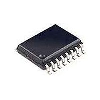
TD340ID STMicroelectronics, TD340ID Datasheet

TD340ID
Specifications of TD340ID
Available stocks
Related parts for TD340ID
TD340ID Summary of contents
Page 1
... This is preliminary information on a new product now in development or undergoing evaluation. Details are subject to change without notice. TD340 FOR DC MOTOR CONTROL PRELIMINARY DATA D SO20 (Plastic Micropackage) ORDER CODE Part Number Temperature Range TD340ID -40 C, +125 Small Outline Package (SO) - also available in Tape & Reel (DT) PIN CONNECTIONS (top view) VBATT 1 20 VOUT 2 19 ...
Page 2
SYSTEM AND INTERNAL BLOCK DIAGRAM VBATT 5V VOUT RESET CWD WD STBY TEMP T IN1 IN2 CF 0V PIN DESCRIPTION Name Pin Type VBATT 1 Power Input GND 11 Ground L1 12 Push Pull Output L2 13 Push Pull Output ...
Page 3
TD340 ABSOLUTE MAXIMUM RATINGS Symbol Parameter V Positive Supply Voltage - Note 1 Batt P Power Dissipation d T Storage Temperature stg ESD Electrostatic Discharge Voltage on pins: IN1, IN2, STBY, WD, CWD, CF, TEMP, VOUT, V digital RESET V ...
Page 4
ELECTRICAL CHARACTERISTICS Vbatt= 12V, Tamb=- 125 C (unless otherwise specified) Symbol Parameter Total Supply Current < T < T min. amb max. I Supply Current in Standby Mode stdby Standby STDBY Pin Voltage for Standby ...
Page 5
TD340 ELECTRICAL CHARACTERISTICS (continued) Vbatt= 12V, Tamb=- 125 C (unless otherwise specified) Symbol Parameter VOLTAGE REGULATOR - Co=220nF - note 2 V Output Voltage out Line Line Regulation Reg Load Load Regulation Reg I Maximum Output Current o ...
Page 6
INTERNAL ELECTRICAL SCHEMATIC AND APPLICATION ENVIRONMENT 6/ CONTROLLER TD340 ...
Page 7
TD340 FUNCTIONAL DESCRIPTION Speed and Direction Control: The TD340 IC provides the necessary interface between an H-Bridge DC-Motor Control configuration and a micro controller. The speed and direction are given by two input signals coming from the microprocessor. Speed Control: ...
Page 8
Figure 2 : PWM Analog and Digital Modes TD340 P 5V IN1 PWM PWM 0V CF ANALOG INPUT PWM OUTPUT + CF (270pF) Active (synchronous) rectification for free-wheel current A motor is an inductive load. When driven in PWM mode, ...
Page 9
TD340 Figure 3 : Synchronous Rectification Principle ex1: Speed: PWM=x% No synchronous rectification 1-x% FULL OFF M x% PWM HIGH DISSIPATION THROUGH FREE WHEEL DIODE! Table 1 : Function Table in Digital and Analog Modes IN1 (V) Stby Disable IN2 ...
Page 10
MOS drivers Output drivers are designed to drive MOS with gate capacitance nF. A small resistor in serial with gate input is recommended to prevent spurious oscillations due to parasitic inductance in conjunction with gate capacitance. ...
Page 11
TD340 Reversed battery active protection In full H-bridge configuration, there is a risk in case of power voltage reversal due to the intrinsic diodes inside the MOS. A passive protection solution is to wire a diode between the H-bridge and ...
Page 12
Microcontroller support For easy system integration, the TD340 provides the following functions regulator, - reset circuit, - watchdog circuit, - standby mode, - temperature indicator. 5V regulator The TD340 provides a 5V regulated voltage at VOUT pin with ...
Page 13
TD340 Watchdog circuit An integrated Watchdog circuit resets the microcontroller when a periodic signal coming from the microcontroller is missing after an externally adjustable Time out delay. Watchdog timeout is adjustable by means of a capacitor Cwd between CWD pin ...
Page 14
Standby mode The TD340 can be put in standby mode under software control. When the STBY pin is driven low, the MOS drivers are switched off and internal charge pump oscillator is stopped. The 5V regulator, the watchdog and reset ...
Page 15
TD340 PERFORMANCE CURVES 5V Regulator Voltage vs Output Current 5.1 Vbatt=16V Vbatt=12V 5.0 4.9 4.8 4.7 Cout=220nF 4.6 4 Iout (m A) Charge Pump Voltage vs Current Vbatt=16V Vbatt=6.5V ...
Page 16
PERFORMANCE CURVES (continued) Vbatt= 12V, unless otherwise specified Supply current 5 4.5 4 3.5 3 2.5 - 100 Reset Threshold (decreasing) 4.4 4.3 4.2 4.1 4.0 3.9 - 100 Under ...
Page 17
TD340 PERFORMANCE CURVES (continued) Vbatt= 12V, unless otherwise specified OSC Output Frequency 1.4 1.2 1.0 0.8 0.6 - 100 High Side Driver output Current (source) 100 - 100 T ...
Page 18
APPLICATION CIRCUIT DIAGRAMS The following schematics show typical application circuits. The first one is a simple, standalone system, while the other one is C driven and includes advanced features like standby mode and reversed battery active protection. Simple standalone system ...
Page 19
TD340 Figure 9: Simple Standalone System . 19/21 ...
Page 20
Figure 10: Complete, C Driven System 20/21 TD340 ...
Page 21
... No license is granted by implication or otherwise under any patent or patent rights of STMicroelectronics. Specifications mentioned in this publication are subject to change witho ut notice. This publ ication supersedes and replaces all information previously supplied ...


