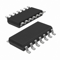
AU5790D14/N,112 NXP Semiconductors, AU5790D14/N,112 Datasheet

AU5790D14/N,112
Specifications of AU5790D14/N,112
935277456112
AU5790D14/N
Related parts for AU5790D14/N,112
AU5790D14/N,112 Summary of contents
Page 1
AU5790 Single wire CAN transceiver Product data Supersedes data of 2001 Jan 31 IC18 Data Handbook hilips Semiconductors INTEGRATED CIRCUITS 2001 May 18 ...
Page 2
Philips Semiconductors Single wire CAN transceiver FEATURES Supports in-vehicle class B multiplexing via a single bus line with ground return 33 kbps CAN bus speed with loading as per J2411 83 kbps high-speed transmission mode Low RFI due to output ...
Page 3
Philips Semiconductors Single wire CAN transceiver BLOCK DIAGRAM TxD 3 NSTB (Mode (Mode 1) RxD 4 2001 May 18 BATTERY (+12V) BAT 1 VOLTAGE TEMP. PROTECTION REFERENCE OUTPUT BUFFER MODE CONTROL RECEIVER PROTECTION 8 GND Figure 1. ...
Page 4
Philips Semiconductors Single wire CAN transceiver SO8 PIN CONFIGURATION 1 TxD NSTB (Mode 0) 2 AU5790 EN (Mode 1) 3 RxD 4 SO8 SO8 PIN DESCRIPTION SYM- PIN DESCRIPTION BOL TxD 1 Transmit data input: high = transmitter passive; low ...
Page 5
Philips Semiconductors Single wire CAN transceiver FUNCTIONAL DESCRIPTION The AU5790 is an integrated line transceiver IC that interfaces a CAN protocol controller to the vehicle’s multiplexed bus line primarily intended for automotive “Class B” multiplexing applications in passenger ...
Page 6
Philips Semiconductors Single wire CAN transceiver ABSOLUTE MAXIMUM RATINGS According to the IEC 134 Absolute Maximum System: operation is not guaranteed under these conditions; all voltages are referenced to pin 8 (GND); positive currents flow into the IC, unless otherwise ...
Page 7
Philips Semiconductors Single wire CAN transceiver DC CHARACTERISTICS –40 C < T < +125 C; 5.5 V < V < –0.3 V < V amb BAT –1 V < V < +16 V; bus load resistor at pin ...
Page 8
Philips Semiconductors Single wire CAN transceiver SYMBOL PARAMETER Pin CANH (continued) –I Bus short circuit current in CANHH high-speed mode I Bus leakage current at loss of CANLG ground (I_CAN_LG = I_CANH + I_RTH) T Thermal shutdown sd T Thermal ...
Page 9
Philips Semiconductors Single wire CAN transceiver Dynamic (AC) CHARACTERISTICS for 33 kbps operation –40 C < T < +125 C; 5.5 V < V < –0.3 V < V amb BAT –1 V < V < +16 V; ...
Page 10
Philips Semiconductors Single wire CAN transceiver SYMBOL PARAMETER Pin TxD (continued) t Transmit delay in high-speed TrHS mode, bus rising edge t Transmit delay in high-speed TfHS mode, bus falling edge Pin RxD t Receive delay in normal mode, DN ...
Page 11
Philips Semiconductors Single wire CAN transceiver TxD 50% CANH RxD 50% NOTE: 1. When AU5790 is in normal, high-speed, or wake-up mode, the transmit delay in rising edge t respectively; the transmit delay in ...
Page 12
Philips Semiconductors Single wire CAN transceiver TEST CIRCUITS S1 NSTB S2 2.4 k NOTES: Opening S3 simulates loss of module ground. Check I_CAN_LG with the following switch positions to simulate loss of ground in all modes open ...
Page 13
Philips Semiconductors Single wire CAN transceiver APPLICATION INFORMATION The information in this section is not part of the IC specification, but is presented for information purposes only. Additional information on single wire CAN networks, application circuits, and thermal management are ...
Page 14
Philips Semiconductors Single wire CAN transceiver THERMAL CHARACTERISTICS The AU5790 provides protection from thermal overload. When the IC junction temperature reaches the threshold ( 155 C), the AU5790 will disable the transmitter drivers, reducing power dissipation to protect the device. ...
Page 15
Philips Semiconductors Single wire CAN transceiver Table 3 shows the maximum power dissipation of an AU5790 without tripping the thermal overload protection, for specified combinations of package, board configuration, and ambient temperature. Table 3. Maximum power dissipation Additional Foil Area ...
Page 16
Philips Semiconductors Single wire CAN transceiver Power Dissipation Power dissipation the major factor determining junction temperature. AU5790 power dissipation in active and passive states are different. The average power dissipation is *Dy + ...
Page 17
Philips Semiconductors Single wire CAN transceiver 500 450 400 350 300 250 200 150 100 AMBIENT TEMPERATURE ( C) Figure 7. Required Thermal Resistance vs. Ambient Temperature and Power Dissipation 2001 May 18 90 ...
Page 18
Philips Semiconductors Single wire CAN transceiver SO8: plastic small outline package; 8 leads; body width 3.9 mm 2001 May 18 18 Product data AU5790 SOT96-1 ...
Page 19
Philips Semiconductors Single wire CAN transceiver SO14: plastic small outline package; 14 leads; body width 3.9 mm 2001 May 18 19 Product data AU5790 SOT108-1 ...
Page 20
Philips Semiconductors Single wire CAN transceiver Data sheet status Product Definitions [1] Data sheet status [2] status Objective data Development This data sheet contains data from the objective specification for product development. Philips Semiconductors reserves the right to change the ...


