PCA9538D,118 NXP Semiconductors, PCA9538D,118 Datasheet
PCA9538D,118
Specifications of PCA9538D,118
935277418118
PCA9538D-T


Related parts for PCA9538D,118


PCA9538D,118 Summary of contents
Page 1
... The PCA9538 is a 16-pin CMOS device that provides 8 bits of General Purpose parallel Input/Output (GPIO) expansion with interrupt and reset for I and was developed to enhance the NXP Semiconductors family of I I/O expanders provide a simple solution when additional I/O is needed for ACPI power switches, sensors, push-buttons, LEDs, fans, etc. The PCA9538 consists of an 8-bit Confi ...
Page 2
... NXP Semiconductors I 8 I/O pins which default to 8 inputs 400 kHz clock frequency I ESD protection exceeds 2000 V HBM per JESD22-A114, 200 V MM per JESD22-A115 and 1000 V CDM per JESD22-C101 I Latch-up testing is done to JEDEC Standard JESD78 which exceeds 100 mA I Offered in three different packages: SO16, TSSOP16 and HVQFN16 3 ...
Page 3
... NXP Semiconductors 5. Pinning information 5.1 Pinning RESET Fig 2. Fig 4. PCA9538_5 Product data sheet 2 8-bit I C-bus and SMBus low power I/O port with interrupt and reset SDA 3 14 SCL 4 13 IO0 INT PCA9538D 5 12 IO1 IO7 IO2 6 11 IO6 IO3 7 10 IO5 ...
Page 4
... NXP Semiconductors 5.2 Pin description Table 2. Symbol A0 A1 RESET IO0 IO1 IO2 IO3 V SS IO4 IO5 IO6 IO7 INT SCL SDA V DD [1] HVQFN16 package die supply ground is connected to both the and board-level performance, the exposed pad needs to be soldered to the board using a corresponding thermal pad on the board, and for proper heat conduction through the board thermal vias need to be incorporated in the printed-circuit board in the thermal pad region ...
Page 5
... NXP Semiconductors 6. Functional description Refer to 6.1 Device address Fig 5. 6.2 Registers 6.2.1 Command byte The command byte is the first byte to follow the address byte during a write transmission used as a pointer to determine which of the registers will be written or read. Table 3. Command 6.2.2 Register 0 - Input Port register This register is a read-only port. It refl ...
Page 6
... NXP Semiconductors 6.2.3 Register 1 - Output Port register This register reflects the outgoing logic levels of the pins defined as outputs by Register 3. Bit values in this register have no effect on pins defined as inputs. Reads from this register return the value that is in the flip-flop controlling the output selection, not the actual pin value ...
Page 7
... NXP Semiconductors 6.2.5 Register 3 - Configuration register This register configures the directions of the I/O pins bit in this register is set, the corresponding port pin is enabled as an input with high-impedance output driver bit in this register is cleared, the corresponding port pin is enabled as an output. At reset, the I/Os are confi ...
Page 8
... NXP Semiconductors 6.6 I/O port When an I/O is configured as an input, FETs Q1 and Q2 are off, creating a high-impedance input. The input voltage may be raised above V If the I/O is configured as an output, then either enabled, depending on the state of the Output Port register. Care should be exercised if an external voltage is applied to an I/O confi ...
Page 9
... NXP Semiconductors 6.7 Bus transactions Data is transmitted to the PCA9538 registers using the write mode as shown in and Figure Figure 9 once a command byte has been sent, the register which was addressed will continue to be accessed by reads until a new command byte has been sent. ...
Page 10
... NXP Semiconductors slave address SDA START condition acknowledge slave address (cont (repeated) START condition Fig 9. Read from register SCL slave address SDA START condition read from port data into DATA 1 port INT t v(INT) This figure assumes the command byte has previously been programmed with 00h. ...
Page 11
... NXP Semiconductors 7. Application design-in information MASTER CONTROLLER SCL SDA INT RESET V SS Device address is 1110 000x for this example. IO0, IO2, IO3 configured as outputs. IO1, IO4, IO5 configured as inputs. IO6, IO7 are not used and need 100 k pull-up resistors to protect them from floating. ...
Page 12
... NXP Semiconductors 7.1 Minimizing I When the I/Os are used to control LEDs, they are normally connected to V resistor as shown in I about 1.2 V less than V I lower than V Designs needing to minimize current consumption, such as battery power applications, should consider maintaining the I/O pins greater than or equal to V Figure 12 than the LED supply voltage by at least 1 ...
Page 13
... NXP Semiconductors 8. Limiting values Table 8. In accordance with the Absolute Maximum Rating System (IEC 60134). Symbol I/O I O(IOn tot T stg T amb T j(max) 9. Static characteristics Table 9. Static characteristics Symbol Parameter Supplies V supply voltage DD I supply current DD I LOW-level standby current stbL ...
Page 14
... NXP Semiconductors Table 9. Static characteristics Symbol Parameter I/Os V LOW-level input voltage IL V HIGH-level input voltage IH I LOW-level output current OL V HIGH-level output voltage OH I input leakage current LI C input capacitance i Interrupt INT I LOW-level output current OL Select inputs A0, A1, RESET V LOW-level input voltage ...
Page 15
... NXP Semiconductors 10. Dynamic characteristics Table 10. Dynamic characteristics Symbol Parameter f SCL clock frequency SCL t bus free time between a STOP and BUF START condition t hold time (repeated) START condition HD;STA t set-up time for a repeated START SU;STA condition t set-up time for STOP condition SU;STO ...
Page 16
... NXP Semiconductors SDA t BUF t LOW SCL t HD;STA P S Fig 14. Definition of timing START protocol condition (S) t SU;STA SCL t BUF SDA t HD;STA Rise and fall times refer Fig 15. I C-bus timing diagram START SCL SDA 30 % RESET IOn Fig 16. Definition of RESET timing ...
Page 17
... NXP Semiconductors Fig 17. Expanded view of read input port register Fig 18. Expanded view of write to output port register PCA9538_5 Product data sheet 2 8-bit I C-bus and SMBus low power I/O port with interrupt and reset SCL SDA t su(D) input t v(INT) INT SCL SDA output Rev. 05 — ...
Page 18
... NXP Semiconductors 11. Test information Fig 19. Test circuitry for switching times Fig 20. Test circuit Table 11. Test t v(Q) PCA9538_5 Product data sheet 2 8-bit I C-bus and SMBus low power I/O port with interrupt and reset V I PULSE GENERATOR R = load resistor load capacitance includes jig and probe capacitance. ...
Page 19
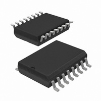
... NXP Semiconductors 12. Package outline SO16: plastic small outline package; 16 leads; body width 7 pin 1 index 1 e DIMENSIONS (inch dimensions are derived from the original mm dimensions) A UNIT max. 0.3 2.45 2.65 mm 0.25 0.1 2.25 0.012 0.096 0.1 inches 0.01 0.004 0.089 Note 1. Plastic or metal protrusions of 0.15 mm (0.006 inch) maximum per side are not included. ...
Page 20
... NXP Semiconductors TSSOP16: plastic thin shrink small outline package; 16 leads; body width 4 pin 1 index 1 DIMENSIONS (mm are the original dimensions) A UNIT max. 0.15 0.95 mm 1.1 0.25 0.05 0.80 Notes 1. Plastic or metal protrusions of 0.15 mm maximum per side are not included. 2. Plastic interlead protrusions of 0.25 mm maximum per side are not included. ...
Page 21
... NXP Semiconductors HVQFN16: plastic thermal enhanced very thin quad flat package; no leads; 16 terminals; body 0.85 mm terminal 1 index area terminal 1 index area DIMENSIONS (mm are the original dimensions) (1) A UNIT max. 0.05 0. 0.2 0.00 0.23 Note 1. Plastic or metal protrusions of 0.075 mm maximum per side are not included. ...
Page 22
... NXP Semiconductors 13. Handling information All input and output pins are protected against ElectroStatic Discharge (ESD) under normal handling. When handling ensure that the appropriate precautions are taken as described in JESD625-A or equivalent standards. 14. Soldering of SMD packages This text provides a very brief insight into a complex technology. A more in-depth account of soldering ICs can be found in Application Note AN10365 “ ...
Page 23
... NXP Semiconductors • Process issues, such as application of adhesive and flux, clinching of leads, board transport, the solder wave parameters, and the time during which components are exposed to the wave • Solder bath specifications, including temperature and impurities 14.4 Reflow soldering Key characteristics in reflow soldering are: • ...
Page 24
... NXP Semiconductors Fig 24. Temperature profiles for large and small components For further information on temperature profiles, refer to Application Note AN10365 “Surface mount reflow soldering description” . 15. Abbreviations Table 14. Acronym ACPI CBT CDM CMOS DUT ESD FET FF GPIO HBM 2 I C-bus ...
Page 25
... Modifications: The format of this data sheet has been redesigned to comply with the new identity guidelines of NXP Semiconductors. • Legal texts have been adapted to the new company name where appropriate. • Pin names changed from “I/On” to “IOn” ...
Page 26
... NXP Semiconductors Table 15. Revision history …continued Document ID Release date • Modifications: Figure 16 “Definition of RESET (continued) – symbol changed from “t – symbol changed from “t – symbol changed from “t • Figure 17 “Expanded view of read input port – symbol changed from “t – ...
Page 27
... Right to make changes — NXP Semiconductors reserves the right to make changes to information published in this document, including without limitation specifications and product descriptions, at any time and without notice ...
Page 28
... NXP Semiconductors 19. Contents 1 General description . . . . . . . . . . . . . . . . . . . . . . 1 2 Features . . . . . . . . . . . . . . . . . . . . . . . . . . . . . . . 1 3 Ordering information . . . . . . . . . . . . . . . . . . . . . 2 4 Block diagram . . . . . . . . . . . . . . . . . . . . . . . . . . 2 5 Pinning information . . . . . . . . . . . . . . . . . . . . . . 3 5.1 Pinning . . . . . . . . . . . . . . . . . . . . . . . . . . . . . . . 3 5.2 Pin description . . . . . . . . . . . . . . . . . . . . . . . . . 4 6 Functional description . . . . . . . . . . . . . . . . . . . 5 6.1 Device address . . . . . . . . . . . . . . . . . . . . . . . . . 5 6.2 Registers 6.2.1 Command byte . . . . . . . . . . . . . . . . . . . . . . . . . 5 6.2.2 Register 0 - Input Port register . . . . . . . . . . . . . 5 6.2.3 Register 1 - Output Port register ...