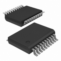
TJA1080ATS/2/T,118 NXP Semiconductors, TJA1080ATS/2/T,118 Datasheet - Page 15

TJA1080ATS/2/T,118
Manufacturer Part Number
TJA1080ATS/2/T,118
Description
IC TXRX FLEXRAY 20-SSOP
Manufacturer
NXP Semiconductors
Datasheet
1.TJA1080ATS2T118.pdf
(49 pages)
Specifications of TJA1080ATS/2/T,118
Package / Case
20-SSOP
Applications
Automotive
Interface
FlexRay
Voltage - Supply
4.75 V ~ 5.25 V
Mounting Type
Surface Mount
Mounting Style
SMD/SMT
Number Of Transmitters
1
Power Supply Requirement
Single
Package Type
SSOP
Operating Temperature Classification
Automotive
Mounting
Surface Mount
Pin Count
20
Operating Temperature (max)
150C
Operating Temperature (min)
-40C
Dual Supply Voltage (typ)
Not RequiredV
Dual Supply Voltage (max)
Not RequiredV
Dual Supply Voltage (min)
Not RequiredV
Lead Free Status / RoHS Status
Lead free / RoHS Compliant
Lead Free Status / RoHS Status
Lead free / RoHS Compliant, Lead free / RoHS Compliant
Other names
568-4813-2
935288151118
935288151118
Available stocks
Company
Part Number
Manufacturer
Quantity
Price
Company:
Part Number:
TJA1080ATS/2/T,118
Manufacturer:
FSC
Quantity:
2 100
NXP Semiconductors
Table 9.
[1]
[2]
[3]
[4]
TJA1080A
Product data sheet
Mode
Star-transmit output
Star-receive
Star-idle
Star-locked
Star-standby
Star-sleep
Pin ERRN provides a serial interface for retrieving diagnostic information.
TRXD lines switched as output if TXEN activity is the initiator for Star-transmit mode.
TRXD lines are switched as input if TRXD activity is the initiator for Star-transmit mode.
Valid if V
Pin signalling in star configuration
IO
and (V
TRXD0 /
TRXD1
input
output
input
input
input
input
6.2.5 Sleep mode
6.3 Operating modes in star configuration
BUF
[3]
[2]
or V
In Sleep mode the transceiver has entered a low power mode. The only difference with
Standby mode is that pin INH1 is also set floating. Sleep mode is also entered if the UV
or UV
In case of an undervoltage on pin V
a positive edge on pin STBN.
The undervoltage flags will be reset by setting the wake flag, and therefore the transceiver
will enter the mode indicated on pins EN and STBN if V
A detailed description of the wake-up mechanism is given in
In star configuration mode control via pins EN and STBN is not possible. The transceiver
autonomously controls the operating modes except in the case of wake-up.
The timing diagram of a transceiver configured in star configuration is illustrated in
Figure
description of the pin signalling in star configuration is given in
If V
flag.
Pin BGE must be HIGH in order to enable the transmitter via pin TXEN. If pin BGE is
LOW, it is not possible to activate the transmitter via pin TXEN. If pin TXEN is not used (no
controller connected to the transceiver), it has to be connected to pin GND in order to
prevent TXEN activity detection.
In all normal modes pin RXD is connected to the output of the normal mode receiver and
therefore represents the data on the bus lines.
ERRN
LOW
error flag
set
error flag
set
BAT
IO
[4]
) are present.
VBAT
and (V
7. The state diagram in star configuration is illustrated in
[1]
flag is set.
HIGH
error flag
reset
error flag
reset
BUF
All information provided in this document is subject to legal disclaimers.
or V
BAT
RXEN
LOW
bus
activity
wake flag
set
Rev. 5 — 24 February 2011
) are within their operating range, pin ERRN will indicate the error
[4]
HIGH
bus idle
wake flag
reset
CC
or V
RXD
LOW
bus
DATA_0
wake flag
set
BAT
[4]
while V
HIGH
bus
DATA_1
or idle
wake flag
reset
IO
IO
is present, the wake flag is set by
is present.
Section
Transmitter INH1
enabled
disabled
Table
Figure
TJA1080A
FlexRay transceiver
9.
6.5.
6. A detailed
© NXP B.V. 2011. All rights reserved.
HIGH
float
float
INH2
HIGH
15 of 49
VIO


