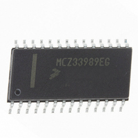
MCZ33989EG Freescale Semiconductor, MCZ33989EG Datasheet - Page 51

MCZ33989EG
Manufacturer Part Number
MCZ33989EG
Description
IC SYSTEM BASIS CHIP CAN 28-SOIC
Manufacturer
Freescale Semiconductor
Datasheet
1.MC33989DWR2.pdf
(66 pages)
Specifications of MCZ33989EG
Applications
*
Interface
*
Voltage - Supply
*
Package / Case
28-SOIC (7.5mm Width)
Mounting Type
Surface Mount
Lead Free Status / RoHS Status
Lead free / RoHS Compliant
Available stocks
Company
Part Number
Manufacturer
Quantity
Price
Part Number:
MCZ33989EG
Manufacturer:
FREESCALE
Quantity:
20 000
Company:
Part Number:
MCZ33989EGR2
Manufacturer:
EXAR
Quantity:
6 247
Analysis: CAN Frame with 11 Bits of Identifier Field at 1
in the identifier field.
Analysis: CAN Frame with 11 Bits of Identifier Field at 0
in the identifier field.
FAILURE ON V2 SUPPLY, CAN BUS LINES AND TX
PIN
V2LOW
must be ON. Two case can be considered:
Analog Integrated Circuit Device Data
Freescale Semiconductor
Figure 42
Figure 43
In order to have proper operation of the CAN interface, V2
• V2 is connected with an external ballast: in case of a V2
• V2 is connected to V1 (no ballast transistor used): V2
over load condition, the flag V2LOW is set in to the SBC
IOR register. This flag is set when V2 is below the 4 V
typical. An interrupt can also be triggered upon a
V2LOW event. When V2 is low, the CAN interface
cannot operate.
will be supplied by the V1 voltage. In case V1 is in an
undervoltage condition (ex V1 below the V1 under
voltage reset, typ 4.6 V), the device will enter the reset
mode. The V2LOW flag will also be set. In this case, the
17 bits are needed to wake-up the SBC.
If the minimum baud rate is used (60 KBaud), TACN = 16.7 µs*17= 284 µs
If 250 KBaud is used, TCAN = 4µs *17= 68 µs.
is the calculation for the TCAN time with only “1”
is the calculation for the TCAN time with only “0”
13 bits are needed to wake-up the SBC.
If the minimum baud rate is used (60 KBaud), TCAN = 16.7 µs*13= 217.1 µs
If 250 KBaud is used: TCAN = 4µs *13= 52 µs
SOF 4 dominant bits
SOF
5 recessive bits
Figure 42. CAN Frame with 11 Bits of Identifier Field at 1
Figure 43. CAN Frame with 11 Bits of Identifier Field at 0
Stuff bit
5 dominant bits
TCAN
Stuff bit
5 recessive bits
Stuff bit
2 dominant bits
TX Permanent Dominant
CAN interface and leads to a disable of the CAN driver. The
TX permanent dominant is detected if TX stays in dominant
(TX low) from more than 360 µs typical. The driver is
automatically re-enabled when TX goes to a high level again.
When a TX permanent dominant is detected, a bit is set into
the SPI register, (bit D2 named TXF in the CAN register). This
bit is latched. In order to clear the bit, two conditions are
necessary:
register will also be set.
Stuff bit 1 recessive bit
3 dominant bit if RTR IDE & DLC=0
A TX permanent dominant condition is detected by the
• No longer “TX permanent failure” AND
• CAN register read operation.
An interrupt can be enabled.The GFAIL flag in the MCR
reset pin is active, and the MCU will not send or receive
any CAN messages.
SUPPLEMENTAL APPLICATION NOTES
SBC wakes up
TYPICAL APPLICATIONS
SBC wakes up
33989
51


