BMA250 Bosch Sensortec, BMA250 Datasheet - Page 22
BMA250
Manufacturer Part Number
BMA250
Description
3-AXIS ACCELEROMETER DIGITAL I/F
Manufacturer
Bosch Sensortec
Series
-r
Specifications of BMA250
Featured Product
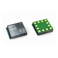
BMA250 - Digital, Triaxial Acceleration Sensor
Axis
X, Y, Z
Acceleration Range
±2g, 4g, 8g, 16g
Sensitivity
256LSB/g, 128LSB/g, 64LSB/g, 16LSB/g
Voltage - Supply
1.62 V ~ 3.6 V
Output Type
I²C™, SPI™
Bandwidth
8Hz ~ 1kHz
Interface
I²C, SPI
Mounting Type
Surface Mount
Package / Case
12-VQFN
Lead Free Status / Rohs Status
Lead free / RoHS Compliant
For Use With
828-1024 - BMA250 DAUGHTERCARD FOR DEV KIT
Other names
828-1023-2
Available stocks
Company
Part Number
Manufacturer
Quantity
Price

Part Number:
BMA250
Manufacturer:
BOSCH/博世
Quantity:
20 000
Company:
Part Number:
BMA250E
Manufacturer:
AME
Quantity:
12 000
Part Number:
BMA250E
Manufacturer:
BOSCH/博世
Quantity:
20 000
Part Number:
BMA250E(F)
Manufacturer:
BOSCH/博世
Quantity:
20 000
Part Number:
BMA250E-F
Manufacturer:
BOSCH/博世
Quantity:
20 000
Company:
Part Number:
BMA250EF
Manufacturer:
TE
Quantity:
30 000
Part Number:
BMA250EF
Manufacturer:
BOSCH/博世
Quantity:
20 000


these values permanently in the non-volatile memory (EEPROM). See section 4.7 Non-volatile
memory for details of the storing procedure.
Each time the device is reset, the compensation values are loaded from the non-volatile
memory into the image registers and used for offset compensation until they are possibly
overwritten using one of the other compensation methods.
4.7 Non-volatile memory
The entire memory of the BMA250 consists of three different kinds of registers: hard-wired,
volatile, and non-volatile. Non-volatile memory is implemented as EEPROM. Part of it can be
both read and written by the user. Access to non-volatile memory is only possible through
(volatile) image registers.
Altogether, there are eight registers (bytes) of EEPROM which are accessible by the customer.
The addresses of the image registers range from 0x38 to 0x3F. While the addresses up to 0x3D
are used for offset compensation (see 4.6 Offset Compensation), addresses 0x3E and 0x3F are
general purpose registers not linked to any sensor-specific functionality.
The content of the EEPROM is loaded to the image registers after a reset (either POR or
softreset) or after a user request which is performed by writing ´1´ to bit (0x33) nvm_load. As
long as the image update is not yet complete, bit (0x33) nvm_load is ´1´, otherwise it is ´0´.
The image registers can be read and written like any other register.
Writing to the EEPROM is a three-step procedure:
Writing to the EEPROM always renews the entire EEPROM contents. It is possible to check the
write status by reading bit (0x33) nvm_rdy. While (0x33) nvm_rdy = ´0´, the write process is still
enduring; if (0x33) nvm_rdy = ´1´, then writing is completed. As long as the write process is
ongoing, no power mode change and no image update is allowed. It is forbidden to write to the
EEPROM while the image update is running, in low-power mode, and in suspend mode.
4.8 Interrupt controller
Seven interrupt engines are integrated in the BMA250. Each interrupt can be independently
enabled and configured. If the condition of an enabled interrupt is fulfilled, the corresponding
status bit is set to ´1´ and the selected interrupt pin is activated. There are two interrupt pins,
INT1 and INT2; interrupts can be freely mapped to any of these pins. The pin state is a logic ´or´
combination of all mapped interrupts.
The interrupt status registers are updated together with writing new data into the acceleration
data registers. If an interrupt is disabled, all active status bits and pins are immediately reset.
Rev. 1.0
© Bosch Sensortec GmbH reserves all rights even in the event of industrial property rights. We reserve all rights of disposal such
as copying and passing on to third parties. BOSCH and the symbol are registered trademarks of Robert Bosch GmbH, Germany.
Note: Specifications within this document are subject to change without notice.
1. Write the new contents to the image registers.
2. Write ´1´ to bit (0x33) nvm_prog_mode in order to unlock the EEPROM.
3. Write ´1´ to bit (0x33) nvm_prog_trig and keep ´1´ in bit (0x33) nvm_prog_mode in order
to trigger the write process.
Page 22 / not for publishing
Data sheet
BMA250
Bosch Sensortec
03 March 2011
Related parts for BMA250
Image
Part Number
Description
Manufacturer
Datasheet
Request
R

Part Number:
Description:
DEVELOPMENT BOARD FOR SENSOR ICS
Manufacturer:
Bosch Sensortec

Part Number:
Description:
BMA150 DAUGHTERCARD FOR DEV KIT
Manufacturer:
Bosch Sensortec
Datasheet:

Part Number:
Description:
BMA140 DAUGHTERCARD FOR DEV KIT
Manufacturer:
Bosch Sensortec
Datasheet:

Part Number:
Description:
BMA020 DAUGHTERCARD FOR DEV KIT
Manufacturer:
Bosch Sensortec

Part Number:
Description:
BMA020 TRIBOX DEMO BOARD W/USB
Manufacturer:
Bosch Sensortec

Part Number:
Description:
BMA150 TRIBOX DEMO BOARD W/USB
Manufacturer:
Bosch Sensortec
Datasheet:

Part Number:
Description:
BMA145 DAUGHTERCARD FOR DEV KIT
Manufacturer:
Bosch Sensortec
Datasheet:

Part Number:
Description:
DAUGHTERCARD FOR DEV KIT BMA120
Manufacturer:
Bosch Sensortec
Datasheet:

Part Number:
Description:
DAUGHTERCARD FOR DEV KIT BMA220
Manufacturer:
Bosch Sensortec
Datasheet:

Part Number:
Description:
BMP085 DAUGHTERCARD FOR DEV KIT
Manufacturer:
Bosch Sensortec
Datasheet:

Part Number:
Description:
DIGITAL BAROMETRIC PRESSURE SNSR
Manufacturer:
Bosch Sensortec
Datasheet:

Part Number:
Description:
ABS. PRESSURE SENSOR ANLG INDUST
Manufacturer:
Bosch Sensortec
Datasheet:

Part Number:
Description:
ACCELEROMETER 3-AXIS SPI/I2C SMD
Manufacturer:
Bosch Sensortec
Datasheet:

Part Number:
Description:
ACCELEROMETER 3-AXIS SPI/I2C SMD
Manufacturer:
Bosch Sensortec
Datasheet:

Part Number:
Description:
3-AXIS ACCELEROMETER ANALOG I/F
Manufacturer:
Bosch Sensortec
Datasheet: