BLF3G21 NXP Semiconductors, BLF3G21 Datasheet
BLF3G21
Specifications of BLF3G21
Available stocks


Related parts for BLF3G21


BLF3G21 Summary of contents
Page 1
... BLF3G21-30 UHF power LDMOS transistor Rev. 01 — 14 February 2007 1. Product profile 1.1 General description 30 W LDMOS power transistor for base station applications at frequencies from HF to 2200 MHz. Table 450 mA Mode of operation CW Two-tone Table Mode of operation PHS CAUTION This device is sensitive to ElectroStatic Discharge (ESD). Therefore care should be taken during transport and handling ...
Page 2
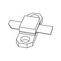
... Ordering information Package Name Description - flanged LDMOST ceramic package; 2 mounting holes; 2 leads Limiting values Parameter Conditions drain-source voltage gate-source voltage drain current storage temperature junction temperature Rev. 01 — 14 February 2007 BLF3G21-30 UHF power LDMOS transistor Simplified outline Symbol 1 [ Min Max - 4.5 ...
Page 3
... Application information = 25 C unless otherwise specified. h Parameter power gain input return loss drain efficiency third order intermodulation distortion power gain drain efficiency Dq power gain drain efficiency Rev. 01 — 14 February 2007 BLF3G21-30 UHF power LDMOS transistor Conditions L(AV L(AV) Min = 0.7 mA ...
Page 4
... NXP Semiconductors 7.1 Ruggedness in class-AB operation The BLF3G21-30 is capable of withstanding a load mismatch corresponding to VSWR = through all phases under the following conditions 2200 MHz at rated load power (dB 450 mA Fig 1. Power gain as function of CW load power; typical values (dB 450 mA 2000 MHz 2000.1 MHz ...
Page 5
... Product data sheet 001aaf794 (pF) (3) (7) (5) 0.5 1.0 f (MHz Fig 6. C 001aaf796 2.1 2.2 f (GHz Fig 8. Load impedance as function of frequency Rev. 01 — 14 February 2007 BLF3G21-30 UHF power LDMOS transistor oss C C iss 10 C rss and C as functions of drain supply iss rss oss voltage ...
Page 6
input Fig 9. Class-AB test circuit for 2 GHz R1 C11 C12 V gate C6 C5 L12 C10 L10 C9 L14 L11 L15 L13 ...
Page 7
... The other side is unetched and serves as a ground plane. See Table 9 for a list of components. Fig 10. Component layout for 2 GHz class-AB test circuit BLF3G21-30_1 Product data sheet 50 mm PH98072 IN C16 PH98072 IN Rev. 01 — 14 February 2007 BLF3G21-30 UHF power LDMOS transistor PH98073 OUT C15 C13 C14 C11 F1 C12 R2 C10 C9 ...
Page 8
... W Rev. 01 — 14 February 2007 BLF3G21-30 UHF power LDMOS transistor Dimensions Catalogue No. 2222 581 16641 2222 037 58101 8DS3/3/8/9-4S2 4330 030 36301 1.9 mm 7 ...
Page 9
... REFERENCES JEDEC EIAJ Rev. 01 — 14 February 2007 BLF3G21-30 UHF power LDMOS transistor 2.21 20.45 5.97 14.27 0.25 0.51 1.96 20 ...
Page 10
... Personal HandyPhone System Radio Frequency Surface-Mount Device Ultra High Frequency Voltage Standing-Wave Ratio Wideband Code Division Multiple Access Data sheet status Product data sheet Rev. 01 — 14 February 2007 BLF3G21-30 UHF power LDMOS transistor Change notice Supersedes - - © NXP B.V. 2007. All rights reserved ...
Page 11
... Trademarks Notice: All referenced brands, product names, service names and trademarks are the property of their respective owners. http://www.nxp.com salesaddresses@nxp.com Rev. 01 — 14 February 2007 BLF3G21-30 UHF power LDMOS transistor © NXP B.V. 2007. All rights reserved ...
Page 12
... Please be aware that important notices concerning this document and the product(s) described herein, have been included in section ‘Legal information’. © NXP B.V. 2007. For more information, please visit: http://www.nxp.com For sales office addresses, please send an email to: salesaddresses@nxp.com All rights reserved. Date of release: 14 February 2007 Document identifier: BLF3G21-30_1 ...