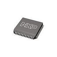
SC28C94A1A NXP Semiconductors, SC28C94A1A Datasheet - Page 34

SC28C94A1A
Manufacturer Part Number
SC28C94A1A
Description
UART Interface IC UART QUAD W/FIFO
Manufacturer
NXP Semiconductors
Type
Quad UARTr
Datasheet
1.SC28C94A1A512.pdf
(39 pages)
Specifications of SC28C94A1A
Number Of Channels
4
Data Rate
1 Mbps
Supply Voltage (max)
5.5 V
Supply Voltage (min)
4.5 V
Supply Current
35 mA
Maximum Operating Temperature
+ 85 C
Minimum Operating Temperature
- 40 C
Package / Case
PLCC-52
Description/function
Quad UART
Mounting Style
SMD/SMT
Operating Supply Voltage
5 V
Lead Free Status / Rohs Status
Details
Other names
SC28C94A1A,512
Available stocks
Company
Part Number
Manufacturer
Quantity
Price
Company:
Part Number:
SC28C94A1A,512
Manufacturer:
NXP Semiconductors
Quantity:
10 000
Company:
Part Number:
SC28C94A1A,518
Manufacturer:
Maxim
Quantity:
21
Company:
Part Number:
SC28C94A1A,518
Manufacturer:
NXP Semiconductors
Quantity:
10 000
Philips Semiconductors
INTERRUPT NOTES
The following is a brief description of the new QUART “Bidding”
interrupt system, interrupt vector and the use of the Global registers.
The new features of the QUARTs have been developed to greatly
reduce the microprocessor time required to service uart interrupts.
Bus cycle times have also been enhanced. By use of the new
Current Interrupt Register (CIR) the speed of a polled system is
also improved. For example programming the SCC2692 to interrupt
on TxRDY and RxFUL would generate four interrupts for every six
characters processed along with at least two additional accesses to
the chip for each interrupt. This amounts to two non–data chip
accesses per character. In the 28C94 this has been reduced to 0.25
non data accesses per character; an eight fold improvement. In
certain conditions use of the global registers will yield a greater
improvement.
The QUART has 18 possible sources which can be programmed to
generate an interrupt:
These sources are encoded in such a way that they generate a
unique value. This value is defined by chip hardwire programming,
user programming, and the source’s present condition. The values
the sources generate are compared (at the X1 clock rate) to a user
defined Interrupt Threshold value contained in the ICR (Interrupt
Control Register). When the source’s value exceeds the threshold
Table 9.
NOTES:
1. The ones and zeros above represent the hardwired positions.
2. Note the format of bits 4:2. They represent the identity of the interrupting source.
3. Bids with the highest number of contiguous MSBs win the bid.
In these identifiers the receivers are biased to have highest priority.
The identifier bits and the channel number bits are hardwired on the
chip. Normally the non–data interrupts would be programmed to a
low value. The programmable fields can, in some cases, make
these sources higher than a full receiver.
2006 Aug 09
4 Receiver channels
4 Transmitter Channels
4 Received ”Break” conditions
4 Change of State Detectors (a total of 8 ports)
2 Counter/Timers
Quad universal asynchronous receiver/transmitter (QUART)
1 1 1
0 1 1
x 1 0
1 0 0
0 0 1
1 0 1
0 0 0
BIT 7
Programmable
0
Programmable
Programmable
Rx Byte count
Rx Byte count
Receiver with error
Receiver without error
Transmitter
Receiver Break detect
Change of State
Counter/Timer
No interrupt
Bidding Format
BIT 6
Tx Byte Count
BIT 5
0
no Error
BIT 4
Error
1
0
1
0
1
BIT 3
1
1
1
0
0
0
BIT 2
1
1
0
0
1
1
34
the interrupt is generated. It is the source’s value which is captured
in the CIR.
The heart of the interrupt speed enhancement is attained by
allowing the interrupting source to encode its channel, interrupt type
and, if appropriate, the number of FIFO bytes requiring service. This
information is coded and transferred the CIR (Current Interrupt
Register) at the time IACKN is asserted or the command ’Update
CIR’ is executed. Upon an interrupt the processor may read this
register and in one access determine the ”who, what and how
much”. This CIR value is used to drive the interrupt vector
modification (when used) and the new ”Global” registers.
“Global” Registers
The ”Global Registers” are effectively pointers which use the
contents of the CIR to direct a read or write operation to Rx or Tx or
other source which is currently interrupting. There are four global
registers defined in the register map:
1. Global Interrupting Byte Count
2. Global Interrupting Channel
3. Global Receive FIFO Register
4. Global Transmit FIFO Register
The global receive and transmit registers operate as an indirect
address. The data read from the global receive register will be that
of the currently interrupting receiver; the data written to the global
transmit register will go to the currently interrupting transmitter. The
interesting point here is that under certain circumstances an
interrupt can be serviced without an interrogation of the chip.
For completeness it should be noted that the global registers are not
physical devices. Reads of the Global Byte and Channel registers
give the Byte count or Channel number, respectively, (right justified)
of the interrupting channel. The CIR data is mapped to these
”registers”.
It would seem that a 11 programmed in the upper counter/timer bits,
for example, would cause it to interrupt nearly all the time.
not true . A counter/timer that has not timed out will not bid. In a
similar fashion a receiver FIFO that is empty or a transmitter FIFO
that is full will not bid
In general terms the threshold value programmed in the ICR
(Interrupt Control Register) will reflect some fill level of the eight
character transmit and receive FIFOs that allow processor service
without underrun or overrun occurring.
Note that interrupt threshold value in the ICR is 6 bits long. This
value is aligned with the bid arbitration logic such that it bids only
BIT 1
Channel No.
Channel No.
Channel No.
Channel No.
Channel No.
Channel No.
BIT 0
Receiver bid With error
Receiver bid No error
Change of State
Receive Break
Counter/Timer
Transmit bid
FUNCTION
SC28C94
Product data sheet
This is


