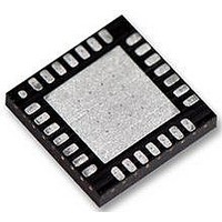
LM4836LQ National Semiconductor, LM4836LQ Datasheet - Page 20

LM4836LQ
Manufacturer Part Number
LM4836LQ
Description
34C6605
Manufacturer
National Semiconductor
Datasheet
1.LM4836LQNOPB.pdf
(28 pages)
Specifications of LM4836LQ
Amplifier Class
AB
No. Of Channels
2
Output Power
2.2W
Supply Voltage Range
2.7V To 5.5V
Load Impedance
3ohm
Operating Temperature Range
-40°C To +85°C
Amplifier Case Style
LLP
Rohs Compliant
No
Available stocks
Company
Part Number
Manufacturer
Quantity
Price
Part Number:
LM4836LQ
Manufacturer:
NS/国半
Quantity:
20 000
www.national.com
Application Information
accommodate this system alert signal, the LM4836’s pin 11
is a mono input that accepts the beep signal. Internal level
detection circuitry at this input monitors the beep signal’s
magnitude. When a signal level greater than V
tected on pin 11, the bridge output amplifiers are enabled.
The beep signal is amplified and applied to the load con-
nected to the output amplifiers. A valid beep signal will be
applied to the load even when MUTE is active. Use the input
resistors connected between the BEEP IN pin and the stereo
input pins to accommodate different beep signal amplitudes.
These resistors are shown as 200kΩ devices in Figure 2.
Use higher value resistors to reduce the gain applied to the
beep signal. The resistors must be used to pass the beep
signal to the stereo inputs. The BEEP IN pin is used only to
detect the beep signal’s magnitude: it does not pass the
signal to the output amplifiers. The LM4836’s shutdown
mode must be deactivated before a system alert signal is
applied to BEEP IN pin.
MICRO-POWER SHUTDOWN
The voltage applied to the SHUTDOWN pin controls the
LM4836’s shutdown function. Activate micro-power shut-
down by applying V
MUTE FUNCTION
The LM4836 mutes the amplifier and DOCK outputs when
V
LM4836 will amplify a system alert (beep) signal whose
magnitude satisfies the BEEP DETECT circuitry. Applying
0V to the MUTE pin returns the LM4836 to normal, unmated
operation. Prevent unanticipated mute behavior by connect-
ing the MUTE pin to V
HP SENSE FUNCTION
Applying a voltage between 4V and V
HP-IN headphone control pin turns off Amp2A and Amp2B,
muting a bridged-connected load. Quiescent current con-
sumption is reduced when the IC is in this single-ended
mode.
Figure 3 shows the implementation of the LM4836’s head-
phone control function. With no headphones connected to
the headphone jack, the R1-R2 voltage divider sets the
voltage applied to the HP-IN pin (pin 16) at approximately
50mV. This 50mV enables Amp1B and Amp2B, placing the
LM4836 in bridged mode operation. The output coupling
capacitor blocks the amplifier’s half supply DC voltage, pro-
tecting the headphones.
The HP-IN threshold is set at 4V. While the LM4836 operates
in bridged mode, the DC potential across the load is essen-
tially 0V. Therefore, even in an ideal situation, the output
swing cannot cause a false single-ended trigger. Connecting
headphones to the headphone jack disconnects the head-
phone jack contact pin from −OUTA and allows R1 to pull the
DD
is applied to pin 5, the MUTE pin. Even while muted, the
SHUTDOWN
Logic High
Logic Low
Logic Low
Logic Low
Logic Low
PIN
DD
TABLE 1. Logic Level Truth Table for SHUTDOWN, HP-IN, and MUX Operation
to the SHUTDOWN pin. When active,
DD
or ground. Do not let pin 5 float.
DD
Logic High
Logic High
HP-IN PIN
Logic Low
Logic Low
(Continued)
to the LM4836’s
X
DD
/2 is de-
20
MUX CHANNEL
SELECT PIN
the LM4836’s micro-power shutdown feature turns off the
amplifier’s bias circuitry, reducing the supply current. The
logic threshold is typically V
shutdown current is achieved by applying a voltage that is as
near as V
that is less than V
Logic Level Truth Table shows the logic signal levels that
activate and deactivate micro-power shutdown and head-
phone amplifier operation.
There are a few ways to control the micro-power shutdown.
These include using a single-pole, single-throw switch, a
microprocessor, or a microcontroller. When using a switch,
connect an external 10kΩ pull-up resistor between the
SHUTDOWN pin and V
SHUTDOWN pin and ground. Select normal amplifier opera-
tion by closing the switch. Opening the switch connects the
SHUTDOWN pin to V
ing micro-power shutdown. The switch and resistor guaran-
tee that the SHUTDOWN pin will not float. This prevents
unwanted state changes. In a system with a microprocessor
or a microcontroller, use a digital output to apply the control
voltage to the SHUTDOWN pin. Driving the SHUTDOWN pin
with active circuitry eliminates the pull up resistor.
HP Sense pin up to V
tion, turns off Amp2A and Amp2B, and mutes the bridged
speaker. The amplifier then drives the headphones, whose
impedance is in parallel with resistor R2 and R3. These
resistors have negligible effect on the LM4836’s output drive
capability since the typical impedance of headphones is
32Ω.
Figure 3 also shows the suggested headphone jack electri-
cal connections. The jack is designed to mate with a three-
wire plug. The plug’s tip and ring should each carry one of
the two stereo output signals, whereas the sleeve should
carry the ground return. A headphone jack with one control
pin contact is sufficient to drive the HP-IN pin when connect-
ing headphones.
A microprocessor or a switch can replace the headphone
jack contact pin. When a microprocessor or switch applies a
voltage greater than 4V to the HP-IN pin, a bridge-connected
speaker is muted and Amp1A and Amp2A drive a pair of
headphones.
Logic High
Logic High
Logic Low
Logic Low
X
DD
as possible to the SHUTDOWN pin. A voltage
DD
DD
DD
may increase the shutdown current.
DD
(MUX INPUT CHANNEL #)
Single-Ended Amplifiers (1)
Single-Ended Amplifiers (2)
. This enables the headphone func-
through the pull-up resistor, activat-
OPERATIONAL MODE
. Connect the switch between the
Micro-Power Shutdown
Bridged Amplifiers (1)
Bridged Amplifiers (2)
DD
/2. The low 0.7 µA typical


