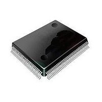
STM32F407VET6 STMicroelectronics, STM32F407VET6 Datasheet - Page 126

STM32F407VET6
Manufacturer Part Number
STM32F407VET6
Description
Microcontrollers (MCU) ARM M4 512 FLASH 168 Mhz 192kB SRAM
Manufacturer
STMicroelectronics
Datasheet
1.STM32F407ZGT6.pdf
(167 pages)
Specifications of STM32F407VET6
Core
ARM Cortex M4
Processor Series
STM32F4
Data Bus Width
32 bit
Maximum Clock Frequency
168 MHz
Program Memory Size
512 KB
Data Ram Size
192 KB
On-chip Adc
Yes
Number Of Programmable I/os
82
Number Of Timers
10
Operating Supply Voltage
1.7 V to 3.6 V
Package / Case
LQFP-100
Mounting Style
SMD/SMT
A/d Bit Size
12 bit
A/d Channels Available
16
Interface Type
CAN, I2C, I2S, SPI, UART
Program Memory Type
Flash
Lead Free Status / Rohs Status
Details
Available stocks
Company
Part Number
Manufacturer
Quantity
Price
Company:
Part Number:
STM32F407VET6
Manufacturer:
ASB
Quantity:
6 700
Company:
Part Number:
STM32F407VET6
Manufacturer:
STMicroelectronics
Quantity:
1
Company:
Part Number:
STM32F407VET6
Manufacturer:
STMicroelectronics
Quantity:
10 000
Part Number:
STM32F407VET6
Manufacturer:
ST
Quantity:
20 000
Company:
Part Number:
STM32F407VET6
Manufacturer:
ST
Quantity:
11 856
Company:
Part Number:
STM32F407VET6.
Manufacturer:
ST
Quantity:
15 000
Electrical characteristics
Figure 51. 12-bit buffered /non-buffered DAC
1. The DAC integrates an output buffer that can be used to reduce the output impedance and to drive external loads directly
5.3.25
126/167
without the use of an external operational amplifier. The buffer can be bypassed by configuring the BOFFx bit in the
DAC_CR register.
FSMC characteristics
Asynchronous waveforms and timings
Figure 52
Table 74
with the following FSMC configuration:
●
●
●
●
In all timing tables, the
AddressSetupTime = 1
AddressHoldTime = 0x1
DataSetupTime = 0x1
BusTurnAroundDuration = 0x0
provide the corresponding timings. The results shown in these tables are obtained
through
Buffered/Non-buffered DAC
Figure 55
12-bit
digital to
analog
converter
T
HCLK
represent asynchronous waveforms and
is the HCLK clock period.
Doc ID 022152 Rev 2
Buffer(1)
DACx_OUT
C
R
LOAD
LOAD
STM32F405xx, STM32F407xx
Table 71
ai17157
through


