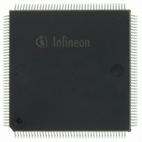
PEB20320H-V34 Infineon Technologies, PEB20320H-V34 Datasheet - Page 38

PEB20320H-V34
Manufacturer Part Number
PEB20320H-V34
Description
IC CONTROLR 32-CH HDLC 160-MQFP
Manufacturer
Infineon Technologies
Datasheet
1.PEB20320H-V34.pdf
(252 pages)
Specifications of PEB20320H-V34
Function
Multichannel Network Interface Controller (MUNICH)
Interface
HDLC, V.110, X.30
Voltage - Supply
5V
Current - Supply
100mA
Operating Temperature
0°C ~ 70°C
Mounting Type
Surface Mount
Package / Case
160-BSQFP
Includes
Automatic Flag Detection, CRC Generation and Checking, Error Detection, Interframe-Time-Fill Change Detection
Lead Free Status / RoHS Status
Contains lead / RoHS non-compliant
Power (watts)
-
Number Of Circuits
-
Other names
PEB20320H-V34
PEB20320H-V34IN
PEB20320H-V34IN
Available stocks
Company
Part Number
Manufacturer
Quantity
Price
Company:
Part Number:
PEB20320H-V34
Manufacturer:
Infineon Technologies
Quantity:
10 000
- Current page: 38 of 252
- Download datasheet (3Mb)
User’s Manual
2.2
A 64-channel DMA controller (32 channels in receive direction and 32 channels in
transmit direction) with buffer chaining capability is integrated in the MUNICH32. It
provides DMA functions for up to 32 full duplex channels and allows data transfer
between the serial interface and an external memory. The MUNICH32 performs long
word by long word transfers on a 32-bit bidirectional data bus (D(31:0)) and addresses
up to 4 GByte of RAM with a 30-bit address bus (A(31:2)). The chip always works as a
system bus master and can be operated in either a Intel or Motorola environment.
MUNICH32 receives commands and data from the host processor via the shared
memory. The host stores the action specification containing configuration initialization
and monitor commands in the memory. Afterwards the host informs the MUNICH32 by
generating an action request pulse (AR line). The MUNICH32 reacts by reading the
action specification and informs the microprocessor by appending the respective
interrupt information to the interrupt queue. In addition, the INT/INT line is activated
during the write access belonging to the interrupt specification.
The timing of the microprocessor interface is established according to the Intel 80386 or
Motorola 68020 processor. The system clock (SCLK) provides the fundamental timing
for the P interface and is the internal device clock. Each bus cycle performs a long word
(B16 = 1) or a word (B16 = 0) transfer and takes four system clock periods in the fastest
case, any number of wait clock cycles can be inserted.
MUNICH32’s architecture is based on a 32-bit data structure. Therefore MUNICH32
performs long word operations preferably. While the word operation mode is selected the
long word operation is divided into two consecutive word operations. In the case of a
read access the data of the two words are connected together to build a 32-bit long word
before processing.
Mode
Intel
Motorola
For a read access first the MSB bytes of a long word will be transferred and then the
LSB bytes via D(15:0).
For a write access first the LSB-bytes of a long word will be transferred and then the
MSB bytes via D(15:0).
The signal B16 cannot be changed dynamically and should be set to ‘1’ in Intel parity
mode (parity mode is not available in 16-bit word Intel mode).
Microprocessor Interface
Operation Mode B16
1
0
0
1
0
0
38
BE(3–0)
0
3
C
0
8
A
H
H
H
H
H
H
Functional Description
Access
long word
MSB word
LSB word
long word
MSB word
LSB word
PEB 20320
01.2000
Related parts for PEB20320H-V34
Image
Part Number
Description
Manufacturer
Datasheet
Request
R

Part Number:
Description:
Multichannel Network Interface Controller For Hdlc
Manufacturer:
Infineon Technologies Corporation
Datasheet:

Part Number:
Description:
Manufacturer:
Infineon Technologies AG
Datasheet:

Part Number:
Description:
Manufacturer:
Infineon Technologies AG
Datasheet:

Part Number:
Description:
Manufacturer:
Infineon Technologies AG
Datasheet:

Part Number:
Description:
Manufacturer:
Infineon Technologies AG
Datasheet:

Part Number:
Description:
Manufacturer:
Infineon Technologies AG
Datasheet:

Part Number:
Description:
Manufacturer:
Infineon Technologies AG
Datasheet:

Part Number:
Description:
Manufacturer:
Infineon Technologies AG
Datasheet:

Part Number:
Description:
16-bit microcontroller with 2x2 KByte RAM
Manufacturer:
Infineon Technologies AG
Datasheet:

Part Number:
Description:
NPN silicon RF transistor
Manufacturer:
Infineon Technologies AG
Datasheet:

Part Number:
Description:
NPN silicon RF transistor
Manufacturer:
Infineon Technologies AG
Datasheet:

Part Number:
Description:
NPN silicon RF transistor
Manufacturer:
Infineon Technologies AG
Datasheet:

Part Number:
Description:
NPN silicon RF transistor
Manufacturer:
Infineon Technologies AG
Datasheet:

Part Number:
Description:
Si-MMIC-amplifier in SIEGET 25-technologie
Manufacturer:
Infineon Technologies AG
Datasheet:

Part Number:
Description:
IGBT Power Module
Manufacturer:
Infineon Technologies AG
Datasheet:


