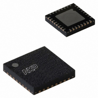
SC16C752BIBS,151 NXP Semiconductors, SC16C752BIBS,151 Datasheet - Page 9

SC16C752BIBS,151
Manufacturer Part Number
SC16C752BIBS,151
Description
IC UART DUAL W/FIFO 32-HVQFN
Manufacturer
NXP Semiconductors
Type
Dual UART with 64-byte FIFOsr
Datasheet
1.SC16C752BIBS151.pdf
(47 pages)
Specifications of SC16C752BIBS,151
Number Of Channels
2, DUART
Package / Case
32-VFQFN Exposed Pad
Features
False-start Bit Detection
Fifo's
64 Byte
Voltage - Supply
2.5V, 3.3V, 5V
With Auto Flow Control
Yes
With False Start Bit Detection
Yes
With Modem Control
Yes
Mounting Type
Surface Mount
Data Rate
5 Mbps
Supply Voltage (max)
5.5 V
Supply Voltage (min)
2.25 V
Supply Current
4.5 mA
Maximum Operating Temperature
+ 85 C
Minimum Operating Temperature
- 40 C
Mounting Style
SMD/SMT
Operating Supply Voltage
2.5 V or 3.3 V or 5 V
Lead Free Status / RoHS Status
Lead free / RoHS Compliant
Lead Free Status / RoHS Status
Lead free / RoHS Compliant, Lead free / RoHS Compliant
Other names
568-3288
935276389151
SC16C752BIBS-S
935276389151
SC16C752BIBS-S
NXP Semiconductors
SC16C752B
Product data sheet
Fig 6.
When CTSn is LOW, the transmitter keeps sending serial data out.
When CTSn goes HIGH before the middle of the last stop bit of the current byte, the transmitter finishes sending the current
byte, but is does not send the next byte.
When CTSn goes from HIGH to LOW, the transmitter begins sending data again.
CTS functional timing
CTSn
6.2.2 Auto-CTS
TXn
6.3 Software flow control
The transmitter circuitry checks CTSn before sending the next data byte. When CTSn is
active, the transmitter sends the next byte. To stop the transmitter from sending the
following byte, CTSn must be de-asserted before the middle of the last stop bit that is
currently being sent. The auto-CTS function reduces interrupts to the host system. When
flow control is enabled, CTSn level changes do not trigger host interrupts because the
device automatically controls its own transmitter. Without auto-CTS, the transmitter sends
any data present in the transmit FIFO and a receiver overrun error may result.
Software flow control is enabled through the enhanced feature register and the modem
control register. Different combinations of software flow control can be enabled by setting
different combinations of EFR[3:0].
Table 3.
EFR[3]
0
1
0
1
X
X
X
1
0
1
EFR[2]
0
0
1
1
X
X
X
0
1
1
Start
Software flow control options (EFR[0:3])
All information provided in this document is subject to legal disclaimers.
byte 0 to 7
5 V, 2.2 V and 2.5 V dual UART, 5 Mbit/s (max.), with 64-byte FIFOs
EFR[1]
X
X
X
X
0
1
0
1
1
1
Rev. 6 — 30 November 2010
Stop
EFR[0]
X
X
X
X
0
0
1
1
1
1
Table 3
TX, RX software flow controls
no transmit flow control
transmit Xon1, Xoff1
transmit Xon2, Xoff2
transmit Xon1, Xon2, Xoff1, Xoff2
no receive flow control
receiver compared Xon1, Xoff1
receiver compares Xon2, Xoff2
transmit Xon1, Xoff1
receiver compares Xon1 and Xon2, Xoff1 and Xoff2
transmit Xon2, Xoff2
receiver compares Xon1 and Xon2, Xoff1 and Xoff2
transmit Xon1, Xon2, Xoff1, Xoff2
receiver compares Xon1 and Xon2, Xoff1 and Xoff2
shows software flow control options.
Start
byte 0 to 7
SC16C752B
002aaa227
Stop
© NXP B.V. 2010. All rights reserved.
9 of 47


