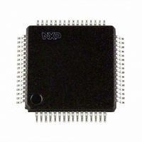
SC16C554DIB64,157 NXP Semiconductors, SC16C554DIB64,157 Datasheet - Page 53

SC16C554DIB64,157
Manufacturer Part Number
SC16C554DIB64,157
Description
IC UART QUAD SOT314-2
Manufacturer
NXP Semiconductors
Datasheet
1.SC16C554DIA68512.pdf
(55 pages)
Specifications of SC16C554DIB64,157
Number Of Channels
4, QUART
Fifo's
16 Byte
Voltage - Supply
2.5V, 3.3V, 5V
With Auto Flow Control
Yes
With Irda Encoder/decoder
Yes
With False Start Bit Detection
Yes
With Modem Control
Yes
With Cmos
Yes
Mounting Type
Surface Mount
Package / Case
64-LQFP
Lead Free Status / RoHS Status
Lead free / RoHS Compliant
Other names
935270063157
SC16C554DIB64
SC16C554DIB64
SC16C554DIB64
SC16C554DIB64
Philips Semiconductors
13. Revision history
Table 29:
9397 750 13132
Product data
Rev Date
05
04
03
02
01
20040510
20030619
20030415
20030313
20020910
Revision history
CPCN
-
-
-
-
-
Description
Product data (9397 750 13132). Supersedes data of 19 June 2003 (9397 750 11616).
Modifications:
Product data (9397 750 11616); ECN 853-2376 30028 of 16 June 2003.
Product data (9397 750 11375); ECN 853-2376 29797 of 11 April 2003.
Product data (9397 750 11002); ECN 853-2376 29627 of 10 March 2003.
Product data; (9397 750 09213); ECN 853-2376 28891 of 10 September 2002.
•
•
•
•
•
•
Figure 6 “LQFP80 pin
from “D6” to “INTD”.
Table 2 “Pin description”
Section 6.4 “Internal
registers...” to “... provides 17 internal registers...”
Section 6.13 “Loop-back mode”
Table 9 “Interrupt Enable Register bits
Table 21 “Enhanced Feature Register bits
bit 4, EFR[4], modified.
– INTSEL description, last sentence: change from “The ST16C654IB64 ...” to “The
– RESET (RESET) description, last sentence: change from “... this pin functions similarly,
– First paragraph:
SC16C654IB64 ...”
bus as an inverted reset interface signal ...” to “... this pin functions similarly, but as an
inverted reset interface signal ...”
– change from “MCR signals DTR and RTS (bits 0-1) are used to control the modem
– Change from “...are connected internally to DTR, RTS, OP1 and OP2.” to “...are
–
CTS and DSR inputs, respectively.” to “MCR signals DTR and RTS (bits 0-1) are used
to control the modem DSR and CTS inputs, respectively.”
connected internally to RTS, DTR, OP2 and OP1.”
Figure 8
Quad UART with 16-byte FIFO and infrared (IrDA) encoder/decoder
and
Figure 9
Rev. 05 — 10 May 2004
registers”, first sentence: change from “... provides 15 internal
configuration.”: change pin 49 from “CSC” to “n.c.”; change pin 74
modified: signals to/from Modem Control Logic block corrected.
description”: description of bit 2, IER[2], modified.
description”: description of bit 6, EFR[6], and of
SC16C554/554D
© Koninklijke Philips Electronics N.V. 2004. All rights reserved.
53 of 55


