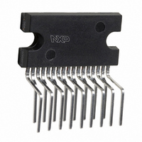
TDA8944J/N1,112 NXP Semiconductors, TDA8944J/N1,112 Datasheet - Page 15

TDA8944J/N1,112
Manufacturer Part Number
TDA8944J/N1,112
Description
IC AMP AUDIO PWR 7W STER 17SIL
Manufacturer
NXP Semiconductors
Type
Class ABr
Datasheet
1.TDA8944JN1112.pdf
(21 pages)
Specifications of TDA8944J/N1,112
Output Type
2-Channel (Stereo)
Package / Case
17-SIL (Bent and Staggered Leads)
Max Output Power X Channels @ Load
7W x 2 @ 8 Ohm
Voltage - Supply
6 V ~ 18 V
Features
Depop, Mute, Short-Circuit and Thermal Protection, Standby
Mounting Type
Through Hole
Product
Class-AB
Output Power
7 W
Available Set Gain
32 dB
Thd Plus Noise
0.03 %
Operating Supply Voltage
12 V
Maximum Power Dissipation
18000 mW
Maximum Operating Temperature
+ 85 C
Mounting Style
Through Hole
Audio Load Resistance
8 Ohms
Input Signal Type
Differential
Minimum Operating Temperature
- 40 C
Output Signal Type
Differential
Supply Type
Single
Supply Voltage (max)
18 V
Supply Voltage (min)
6 V
Lead Free Status / RoHS Status
Lead free / RoHS Compliant
Lead Free Status / RoHS Status
Lead free / RoHS Compliant, Lead free / RoHS Compliant
Other names
568-3462-5
935262855112
TDA8944JU
935262855112
TDA8944JU
15. Test information
Philips Semiconductors
9397 750 06861
Product specification
14.2 Thermal behaviour and heatsink calculation
15.1 Quality information
15.2 Test conditions
The measured maximum thermal resistance of the IC package, R
A calculation for the heatsink can be made, with the following parameters:
At V
see
dissipation - is: 150 – 50 = 100 C.
The calculation above is for an application at worstcase (stereo) sine-wave output
signals. In practice music signals will be applied, which decreases the maximum
power dissipation to approximately half of the sine-wave power dissipation (see
Section
To increase the lifetime of the IC, T
heatsink of approximately 12 K/W for music signals.
The General Quality Specification for Integrated Circuits, SNW-FQ-611D is
applicable.
T
unless otherwise specified.
Remark: In the graphs as function of frequency no bandpass filter was applied; see
Figure
amb
T
V
T
R
including the heatsink. In the heatsink calculations the value of R
P
R
R
P
R
R
amb(max)
j(max)
CC
th(tot)
th(tot)
th(h-a)
th(tot)
th(h-a)
CC
Figure
= 25 C; V
R
R
= 12 V and R
7,
= 12 V and R
th(tot)
th(tot)
8.2.2). This allows for the use of a smaller heatsink:
= 150 C.
is the total thermal resistance between the junction and the ambient
= 100/8 = 12.5 K/W
= 100/4 = 25 K/W
= R
= R
12
11. For T
= 50 C
and 13.
= 100 C
= 100 C
th(tot)
th(tot)
CC
Rev. 02 — 14 February 2000
– R
– R
= 12 V; f = 1 kHz; R
L
j(max)
L
= 8
th(j-mb)
th(j-mb)
= 8
= 150 C the temperature raise - caused by the power
= 12.5 – 6.9 = 5.6 K/W.
the measured worstcase sine-wave dissipation is 8 W;
= 25 – 6.9 = 18.1 K/W.
j(max)
L
should be reduced to 125 C. This requires a
= 8 ; audio pass band 22 Hz to 22 kHz;
2 x 7 W stereo BTL audio amplifier
© Philips Electronics N.V. 2000. All rights reserved.
TDA8944J
th(j-mb)
th(mb-h)
is 6.9 K/W.
is ignored.
15 of 21


