TDA7386 STMicroelectronics, TDA7386 Datasheet - Page 11
TDA7386
Manufacturer Part Number
TDA7386
Description
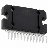
IC AMP AUDIO PWR 45W 25FLEXIWATT
Manufacturer
STMicroelectronics
Type
Class ABr
Datasheet
1.TDA7386.pdf
(14 pages)
Specifications of TDA7386
Output Type
4-Channel (Quad)
Max Output Power X Channels @ Load
45W x 4 @ 4 Ohm
Voltage - Supply
8 V ~ 18 V
Features
Mute, Short-Circuit and Thermal Protection, Standby
Mounting Type
Through Hole
Package / Case
25-Flexiwatt (bent and staggered leads)
Lead Free Status / RoHS Status
Contains lead / RoHS non-compliant
Other names
497-2175-5
Available stocks
Company
Part Number
Manufacturer
Quantity
Price

Part Number:
TDA7386
Manufacturer:
ST
Quantity:
20 000
Part Number:
TDA7386-1LF
Manufacturer:
ST
Quantity:
20 000
Part Number:
TDA7386G
Manufacturer:
ST
Quantity:
20 000


TDA7386
3
3.1
3.2
3.3
Application hints
Referred to the circuit of
SVR
Besides its contribution to the ripple rejection, the SVR capacitor governs the turn ON/OFF
time sequence and, consequently, plays an essential role in the pop optimization during
ON/OFF transients.
To conveniently serve both needs, ITS MINIMUM RECOMMENDED VALUE IS 10μF.
Input stage
The TDA7386’s inputs are ground-compatible and can stand very high input signals (±8Vpk)
without any performances degradation.
If the standard value for the input capacitors (0.1μF) is adopted, the low frequency cut-off
will amount to 16 Hz.
Standby and muting
Standby and muting facilities are both CMOS-compatible. If unused, a straight connection to
Vs of their respective pins would be admissible.
Conventional/low-power transistors can be employed to drive muting and stand-by pins in
absence of true CMOS ports or microprocessors. R-C cells have always to be used in order
to smooth down the transitions for preventing any audible transient noises.
Since a DC current of about 10 µA normally flows out of pin 22, the maximum allowable
muting-series resistance (R
capacitor reasonably small (about 1µF).
If R
to above the 1.5 V threshold voltage and the device will consequently fail to turn OFF when
the mute line is brought down.
About the stand-by, the time constant to be assigned in order to obtain a virtually pop-free
transition has to be slower than 2.5V/ms.
2
is higher than recommended, the involved risk will be that the voltage at pin 22 may rise
Figure
2
) is 70 KΩ, which is sufficiently high to permit a muting
3.
Application hints
11/14
Related parts for TDA7386
Image
Part Number
Description
Manufacturer
Datasheet
Request
R

Part Number:
Description:
STMicroelectronics [RIPPLE-CARRY BINARY COUNTER/DIVIDERS]
Manufacturer:
STMicroelectronics
Datasheet:
Part Number:
Description:
STMicroelectronics [LIQUID-CRYSTAL DISPLAY DRIVERS]
Manufacturer:
STMicroelectronics
Datasheet:

Part Number:
Description:
BOARD EVAL FOR MEMS SENSORS
Manufacturer:
STMicroelectronics
Datasheet:
Part Number:
Description:
NPN TRANSISTOR POWER MODULE
Manufacturer:
STMicroelectronics
Datasheet:
Part Number:
Description:
TURBOSWITCH ULTRA-FAST HIGH VOLTAGE DIODE
Manufacturer:
STMicroelectronics
Datasheet:
Part Number:
Description:
Manufacturer:
STMicroelectronics
Datasheet:
Part Number:
Description:
DIODE / SCR MODULE
Manufacturer:
STMicroelectronics
Datasheet:
Part Number:
Description:
DIODE / SCR MODULE
Manufacturer:
STMicroelectronics
Datasheet:
Part Number:
Description:
Search -----> STE16N100
Manufacturer:
STMicroelectronics
Datasheet:
Part Number:
Description:
Search ---> STE53NA50
Manufacturer:
STMicroelectronics
Datasheet:
Part Number:
Description:
NPN Transistor Power Module
Manufacturer:
STMicroelectronics
Datasheet:
Part Number:
Description:
DIODE / SCR MODULE
Manufacturer:
STMicroelectronics
Datasheet: