TFA9843BJ/N1,112 NXP Semiconductors, TFA9843BJ/N1,112 Datasheet
TFA9843BJ/N1,112
Specifications of TFA9843BJ/N1,112
935275793112
TFA9843BJ


Related parts for TFA9843BJ/N1,112


TFA9843BJ/N1,112 Summary of contents
Page 1
TFA9843BJ 2-channel audio amplifier (SE Rev. 01 — 4 May 2004 1. General description The TFA9843BJ contains two identical audio power amplifiers. The TFA9843BJ can be used as two Single-Ended (SE) channels with a fixed ...
Page 2
Philips Semiconductors 4. Quick reference data Table 1: Symbol Parameter stb P o THD G v SVRR 5. Ordering information Table 2: Type number Package TFA9843BJ 9397 750 12846 Preliminary data sheet Quick reference data ...
Page 3
Philips Semiconductors 6. Block diagram Fig 1. Block diagram. 7. Pinning information 7.1 Pinning Fig 2. Pin configuration. 9397 750 12846 Preliminary data sheet IN1 IN2 CIV V REF STANDBY ...
Page 4
Philips Semiconductors 7.2 Pin description Table 3: Symbol IN2 OUT2 CIV IN1 GND SVR MODE OUT1 Functional description 8.1 Input configuration The input cut-off frequency is cut off – Application cut off ...
Page 5
Philips Semiconductors 8.2.2 Headroom Typical CD music requires at least 12 dB (factor 15.85) dynamic headroom, compared to the average power output, for transferring the loudest parts without distortion Level (ALL) music power ...
Page 6
Philips Semiconductors 8.4 Supply voltage ripple rejection The Supply Voltage Ripple Rejection (SVRR) is measured with an electrolytic capacitor of 150 F on pin SVR using a bandwidth kHz. as function of the frequency. A ...
Page 7
Philips Semiconductors 11. Static characteristics Table 8: Static characteristics amb L Symbol Parameter V supply voltage CC I quiescent supply current q I standby supply current ...
Page 8
Philips Semiconductors 100 mV Fig 4. AC output voltage as function ...
Page 9
Philips Semiconductors ( THD = kHz. L Fig 8. Output power as function of supply voltage (dB) 20 ...
Page 10
Philips Semiconductors 13. Application information 13.1 Application diagram 100 270 7.5 V BC547 2.2 F micro- BC547 controller 1.5 k Fig 12. Application diagram. Remark: Switching inductive loads, the output voltage can rise ...
Page 11
Philips Semiconductors Fig 13. Printed-circuit board layout (single-sided); components view. 13.2.2 Power supply decoupling Proper supply bypassing is critical for low-noise performance and high supply voltage ripple rejection. The respective capacitor location should be as close as possible to the ...
Page 12
Philips Semiconductors R is the total thermal resistance between the junction and the ambient including the th(tot) heatsink. This can be calculated using the maximum temperature increase divided by the power dissipation: R th(tot and ...
Page 13
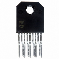
Philips Semiconductors 15. Package outline DBS9P: plastic DIL-bent-SIL power package; 9 leads (lead length 12/11 mm); exposed die pad DIMENSIONS (mm are the original dimensions) (2) (1) (2) UNIT ...
Page 14
Philips Semiconductors 16. Soldering 16.1 Introduction to soldering through-hole mount packages This text gives a brief insight to wave, dip and manual soldering. A more in-depth account of soldering ICs can be found in our Data Handbook IC26; Integrated Circuit ...
Page 15
Philips Semiconductors 17. Revision history Table 11: Revision history Document ID Release date TFA9843BJ_1 20040504 9397 750 12846 Preliminary data sheet Data sheet status Change notice Preliminary data - Rev. 01 — 4 May 2004 TFA9843BJ 2-channel audio amplifier (2 ...
Page 16
Philips Semiconductors 18. Data sheet status [1] Level Data sheet status Product status I Objective data Development II Preliminary data Qualification III Product data Production [1] Please consult the most recently issued data sheet before initiating or completing a design. ...
Page 17
Philips Semiconductors 22. Contents 1 General description . . . . . . . . . . . . . . . . . . . . . . 1 2 Features . . . . . . . . ...