TDA2030V STMicroelectronics, TDA2030V Datasheet
TDA2030V
Specifications of TDA2030V
Available stocks


Related parts for TDA2030V


TDA2030V Summary of contents
Page 1
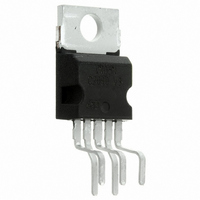
... Differential input voltage i Output peak current (internally limited Power dissipation at T tot Stoprage and junction temperature stg j TYPICAL APPLICATION June 1998 14W Hi-Fi AUDIO AMPLIFIER 14V Parameter = 90 C case TDA2030 Pentawatt ORDERING NUMBERS : TDA2030H TDA2030V Value 18 (36 3.5 20 -40 to 150 Unit 1/12 ...
Page 2
TDA2030 PIN CONNECTION (top view) TEST CIRCUIT 2/ OUTPUT -V S INVERTING INPUT NON INVERTING INPUT ...
Page 3
THERMAL DATA Symbol R Thermal resistance junction-case th j-case ELECTRICAL CHARACTERISTICS (Refer to the test circuit, V specified) for single Supply refer to fig 28V Symbol Parameter V Supply voltage s I Quiescent drain current d I ...
Page 4
TDA2030 Figure 1. Output power vs. supply voltage F ig ure 4. Di stortion vs. output power Fi gure 7. Distor tion vs. frequency 4/12 Figure 2. Output power vs. supply voltage Fi gure 5. Distor tion vs. output power ...
Page 5
Figure 10. Supply voltage rejection vs. voltage gain APPLICATION INFORMATION Figure 13. Typical amplifier with split power supply Figure 11. Power dissipa- tion and efficiency vs. output power Figure 14. P.C. board and component layout for the circuit of fig. ...
Page 6
TDA2030 APPLICATION INFORMATION (continued) Figure 15. Typical amplifier with single power supply Figure 17. Bridge amplifier configuration with split power supply (P 6/12 Figure 16. P.C. board and component layout for the circuit of fig scale) ...
Page 7
PRACTICAL CONSIDERATIONS Printed circuit board The layout shown in Fig. 16 should be adopted by the designers. If different layouts are used, the ground points of input 1 and input 2 must be well decoupled from the ground return of ...
Page 8
TDA2030 SINGLE SUPPLY APPLICATION Recomm. Component value R1 150 100 100 0 100 ...
Page 9
SHORT CIRCUIT PROTECTION The TDA2030 has an original circuit which limits the current of the output transistors. Fig. 18 shows that the maximum output current is a function of the collector emitter voltage; hence the output transis- tors work within ...
Page 10
TDA2030 Figure 20. Output power and rre nt vs. case temperature ( Figure 23. Example of heat-sink 10/12 Figure 21. Output power and d rai n c urr en t vs. ca ...
Page 11
PENTAWATT PACKAGE MECHANICAL DATA DIM. MIN 2.4 D1 1.2 E 0.35 E1 0. 3 10.05 L 17.55 L1 15.55 L2 21 2.6 L6 15.1 ...
Page 12
... No license is granted by implication or otherwise under any patent or patent rights of STMicroelectronics. Specification mentioned in this publication are subject to change without notice. This publication supersedes and replaces all information previously supplied. STMicroelectronics products are not authorized for use as critical components in life support devices or systems without express written approval of STMicroelectronics ...