LM4810LD/NOPB National Semiconductor, LM4810LD/NOPB Datasheet - Page 12
LM4810LD/NOPB
Manufacturer Part Number
LM4810LD/NOPB
Description
IC AMP AUDIO PWR .105W STER 8LLP
Manufacturer
National Semiconductor
Series
Boomer®r
Type
Class ABr
Datasheet
1.LM4810MMNOPB.pdf
(18 pages)
Specifications of LM4810LD/NOPB
Output Type
Headphones, 2-Channel (Stereo)
Max Output Power X Channels @ Load
105mW x 2 @ 16 Ohm
Voltage - Supply
2 V ~ 5.5 V
Features
Depop, Shutdown, Thermal Protection
Mounting Type
Surface Mount
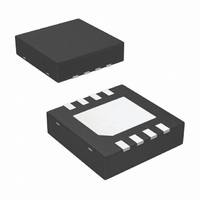
Package / Case
8-LLP
Lead Free Status / RoHS Status
Lead free / RoHS Compliant
Other names
LM4810LD
LM4810LDTR
LM4810LDTR
Available stocks
Company
Part Number
Manufacturer
Quantity
Price
Company:

Part Number:
LM4810LD/NOPB
Manufacturer:
TI/NSC
Quantity:
18 720


www.national.com
Application Information
creased, the load impedance increased or T
the typical application of a 5V power supply, with a 32Ω load,
the maximum ambient temperature possible without violating
the maximum junction temperature is approximately 133.2˚C
provided that device operation is around the maximum
power dissipation point. Power dissipation is a function of
output power and thus, if typical operation is not around the
maximum power dissipation point, the ambient temperature
may be increased accordingly. Refer to the Typical Perfor-
mance Characteristics curves for power dissipation infor-
mation for lower output powers.
POWER SUPPLY BYPASSING
As with any power amplifier, proper supply bypassing is
critical for low noise performance and high power supply
rejection. Applications that employ a 5V regulator typically
use a 10µF in parallel with a 0.1µF filter capacitors to stabi-
lize the regulator’s output, reduce noise on the supply line,
and improve the supply’s transient response. However, their
presence does not eliminate the need for a local 1.0µF
tantalum bypass capacitance connected between the
LM4810’s supply pins and ground. Keep the length of leads
and traces that connect capacitors between the LM4810’s
power supply pin and ground as short as possible. Connect-
ing a 4.7µF capacitor, C
ground improves the internal bias voltage’s stability and
improves the amplifier’s PSRR. The PSRR improvements
increase as the bypass pin capacitor value increases. Too
large, however, increases the amplifier’s turn-on time. The
selection of bypass capacitor values, especially C
on desired PSRR requirements, click and pop performance
(as explained in the section, Selecting Proper External
Components), system cost, and size constraints.
SELECTING PROPER EXTERNAL COMPONENTS
Optimizing the LM4810’s performance requires properly se-
lecting external components. Though the LM4810 operates
well when using external components with wide tolerances,
best performance is achieved by optimizing component val-
ues.
The LM4810 is unity-gain stable, giving a designer maximum
design flexibility. The gain should be set to no more than a
given application requires. This allows the amplifier to
achieve minimum THD+N and maximum signal-to-noise ra-
tio. These parameters are compromised as the closed-loop
gain increases. However, low gain demands input signals
with greater voltage swings to achieve maximum output
power. Fortunately, many signal sources such as audio
CODECs have outputs of 1V
the Audio Power Amplifier Design section for more infor-
mation on selecting the proper gain.
Input and Output Capacitor Value Selection
Amplifying the lowest audio frequencies requires high value
input and output coupling capacitors (C
A high value capacitor can be expensive and may compro-
mise space efficiency in portable designs. In many cases,
however, the speakers used in portable systems, whether
internal or external, have little ability to reproduce signals
below 150Hz. Applications using speakers with this limited
frequency response reap little improvement by using high
value input and output capacitors.
Besides affecting system cost and size, C
the LM4810’s click and pop performance. The magnitude of
B
, between the BYPASS pin and
RMS
(2.83V
I
and C
P-P
(Continued)
i
). Please refer to
has an effect on
A
O
reduced. For
in Figure 1).
B
, depends
12
the pop is directly proportional to the input capacitor’s size.
Thus, pops can be minimized by selecting an input capacitor
value that is no higher than necessary to meet the desired
−3dB frequency. Please refer to the Optimizing Click and
Pop Reduction Performance section for a more detailed
discussion on click and pop performance.
As shown in Figure 1, the input resistor, R
capacitor, C
quency that is found using Equation (3). In addition, the
output load R
high pass filter cutoff frequency defined by Equation (4).
Also, careful consideration must be taken in selecting a
certain type of capacitor to be used in the system. Different
types of capacitors (tantalum, electrolytic, ceramic) have
unique performance characteristics and may affect overall
system performance.
Bypass Capacitor Value Selection
Besides minimizing the input capacitor size, careful consid-
eration should be paid to the value of C
connected to the BYPASS pin. Since C
fast the LM4810 settles to quiescent operation, its value is
critical when minimizing turn-on pops. The slower the
LM4810’s outputs ramp to their quiescent DC voltage (nomi-
nally 1/2 V
equal to 4.7µF along with a small value of C
0.1µF to 0.47µF), produces a click-less and pop-less shut-
down function. As discussed above, choosing C
than necessary for the desired bandwith helps minimize
clicks and pops.
OPTIMIZING CLICK AND POP REDUCTION
PERFORMANCE
The LM4810 contains circuitry that minimizes turn-on and
shutdown transients or “clicks and pop”. For this discussion,
turn-on refers to either applying the power supply voltage or
when the shutdown mode is deactivated. During turn-on, the
LM4810’s internal amplifiers are configured as unity gain
buffers. An internal current source charges up the capacitor
on the BYPASS pin in a controlled, linear manner. The gain
of the internal amplifiers remains unity until the voltage on
the BYPASS pin reaches 1/2 V
the BYPASS pin is stable, the device becomes fully opera-
tional. During device turn-on, a transient (pop) is created
from a voltage difference between the input and output of the
amplifier as the voltage on the BYPASS pin reaches 1/2 V
For this discussion, the input of the amplifier refers to the
node between R
the voltage applied to the BYPASS pin. During turn-on, the
buffer-configured amplifier output charges the input capaci-
tor, C
delays the charging time of C
difference between the input and output that results in a
transient (pop). Higher value capacitors need more time to
reach a quiescent DC voltage (usually 1/2 V
charged with a fixed current. Decreasing the value of C
R
desired -3dB frequency.
Although the BYPASS pin current cannot be modified,
changing the size of C
I
will minimize the turn-on pops at the expense of the
I
, through the input resistor, R
DD
I
, produce a −3dB high pass filter cutoff fre-
L
), the smaller the turn-on pop. Choosing C
, and the output capacitor C
I
and C
f
B
O-3db
f
I
I-3db
alters the device’s turn-on time and
. Ideally, the input and output track
=1/2πR
=1/2πR
I
DD
thereby causing the voltage
. As soon as the voltage on
L
I
C
C
I
O
I
. This input resistor
B
O
, produce a -3db
B
determines how
i
I
, the capacitor
(in the range of
and the input
i
DD
no larger
) when
I
and
DD
(3)
(4)
B
.
Related parts for LM4810LD/NOPB
Image
Part Number
Description
Manufacturer
Datasheet
Request
R

Part Number:
Description:
Dual 105mW Headphone Amplifier with Active-High Shutdown Mode
Manufacturer:
National Semiconductor
Datasheet:
Part Number:
Description:
National Semiconductor [8-Bit D/A Converter]
Manufacturer:
National Semiconductor
Datasheet:
Part Number:
Description:
National Semiconductor [Media Coprocessor]
Manufacturer:
National Semiconductor
Datasheet:
Part Number:
Description:
Digitally Controlled Tone and Volume Circuit with Stereo Audio Power Amplifier, Microphone Preamp Stage and National 3D Sound
Manufacturer:
National Semiconductor
Datasheet:
Part Number:
Description:
Digitally Controlled Tone and Volume Circuit with Stereo Audio Power Amplifier, Microphone Preamp Stage and National 3D Sound
Manufacturer:
National Semiconductor
Datasheet:
Part Number:
Description:
AC97 Rev 2 Codec with Sample Rate Conversion and National 3D Sound
Manufacturer:
National Semiconductor
Part Number:
Description:
Manufacturer:
National Semiconductor
Datasheet:
Part Number:
Description:
Manufacturer:
National Semiconductor
Datasheet:
Part Number:
Description:
General Purpose, Low Voltage, Low Power, Rail-to-Rail Output Operational Amplifiers
Manufacturer:
National Semiconductor
Datasheet:
Part Number:
Description:
8-bit 20 MSPS flash A/D converter.
Manufacturer:
National Semiconductor
Datasheet:
Part Number:
Description:
Low Noise Quad Operational Amplifier
Manufacturer:
National Semiconductor
Datasheet:
Part Number:
Description:
Quad Differential Line Receivers
Manufacturer:
National Semiconductor
Datasheet:
Part Number:
Description:
Quad High Speed Trapezoidal? Bus Transceiver
Manufacturer:
National Semiconductor
Datasheet:
Part Number:
Description:
Dual Line Receiver
Manufacturer:
National Semiconductor
Datasheet: