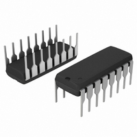
SA571NG ON Semiconductor, SA571NG Datasheet - Page 6

SA571NG
Manufacturer Part Number
SA571NG
Description
IC COMPANDOR DUAL GAIN 16-DIP
Manufacturer
ON Semiconductor
Type
Compandorr
Datasheet
1.SA571NG.pdf
(11 pages)
Specifications of SA571NG
Applications
Cellular Radio, Players
Mounting Type
Through Hole
Package / Case
16-DIP (0.300", 7.62mm)
Product
General Purpose Audio Amplifiers
Operating Supply Voltage
6 V to 18 V
Supply Current
4.2 mA
Maximum Power Dissipation
400 mW
Maximum Operating Temperature
+ 85 C
Mounting Style
Through Hole
Minimum Operating Temperature
- 40 C
Supply Voltage (max)
18 V
Supply Voltage (min)
6 V
Operating Temperature (min)
-40C
Operating Temperature (max)
85C
Operating Temperature Classification
Industrial
Mounting
Through Hole
Pin Count
16
Package Type
PDIP
Lead Free Status / RoHS Status
Lead free / RoHS Compliant
Other names
SA571NG
SA571NGOS
SA571NGOS
Available stocks
Company
Part Number
Manufacturer
Quantity
Price
Company:
Part Number:
SA571NG
Manufacturer:
BCD
Quantity:
12 000
Part Number:
SA571NG
Manufacturer:
ON/安森美
Quantity:
20 000
expandor. The input signal, V
both the rectifier and the DG cell. When the input signal
drops by 6.0 dB, the gain control current will drop by a factor
of 2, and so the gain will drop 6.0 dB. The output level at
V
expansion.
essentially an expandor placed in the feedback loop of the op
amp. The DG cell is setup to provide AC feedback only, so
a separate DC feedback loop is provided by the two R
C
output of the op amp. The output will bias to:
used. External resistors may be placed in series with R
(which will affect the gain), or in parallel with R
DC bias to any desired value.
V
DC
OUT
IN
Figure 6 shows how the circuit is hooked up to realize an
Figure 7 shows the hook−up for a compressor. This is
The output of the expander will bias up to:
The output will bias to 3.0 V when the internal resistors are
. The values of R
NOTE:
will thus drop 12 dB, giving us the desired 2−to−1
V
*C
*C
OUT
V
IN1
OUT
IN2
V
DC +
V
GAIN +
I
*EXTERNAL COMPONENTS
OUT
B
Figure 6. Basic Expander
DC + 1 ) 20kW
OUT
= 140mA
R
DC + 1 )
R
DC +
1
2
DC
1 )
2 R
will determine the DC bias at the
DG
R
3
30kW
1
1 )
R
V
IN
*C
R
IN
DC1
R
, is applied to the inputs of
2
30kW
RECT
(avg)
R
DCTOT
I
B
4
R
R
R
) R
1.8V + 3.0V
4
3
4
2
V
DC2
1.8V
REF
−
+
R
3
V
V
4
REF
REF
to raise the
DC
http://onsemi.com
V
OUT
and
3
,
SA571
6
Circuit Details − Rectifier
averaging rectifier. The input current to the summing node
of the op amp, V
amp. If we can mirror the op amp output current into a
unipolar current, we will have an ideal rectifier. The output
current is averaged by R
constant, and then mirrored with a gain of 2 to become I
the gain control current.
Figure 8 shows the concept behind the full−wave
V
IN
C
NOTE: GAIN +
V
IN
IN
Figure 8. Rectifier Concept
Figure 7. Basic Compressor
R
*
1
IN
R
R
3
I
*EXTERNAL COMPONENTS
4
/R
B
= 140mA
1
−
+
V
, is supplied by the output of the op
I = V
R
REF
5
DC
, CR, which set the averaging time
−
+
IN
*
C
DG
2R
R
R
/ R
1
3
C
C
1
R
V
DC
RECT
2
INavg
R
I
*
V+
R
DC
B
R
2
1
R
10kW
*
*
5
1
2
V
I
G
OUT
C
F
*
G
,


