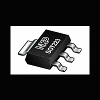
BT131W-600 NXP Semiconductors, BT131W-600 Datasheet

BT131W-600
Available stocks
Related parts for BT131W-600
BT131W-600 Summary of contents
Page 1
... D D ATA SHEET BT131W series Triacs logic level Product specification DISCRETE SEMICONDUCTORS January 2004 ...
Page 2
... /dt = 0.2 A/μs G T2+ G+ T2+ G- T2- G- T2- G+ over any 20 ms period 1 Product specification BT131W series MAX. MAX. UNIT BT131W- 500 600 500 600 1 1 12.5 12.5 SYMBOL T2 MIN. MAX. -500 -600 500 ...
Page 3
... 125 ˚C; DM DRM(max) j exponential waveform kΩ 400 125 ˚ /dt = 0.5 A/ms com DRM(max / A/μ Product specification BT131W series MIN. TYP. MAX 156 - - 70 - MIN. TYP. MAX. T2 0 1 1.4 3 ...
Page 4
... Fig.5. Maximum permissible repetitive rms on-state , for current I p ≤ 20ms TSM time initial = 25 °C max Number of cycles at 50Hz V 3 Product specification BT131W series -50 0 versus solder point temperature T IT(RMS 2.5 2.0 1.5 1 0.5 0 0.01 0.1 1 surge duration / s ...
Page 5
... 1000 100 10 1 100 150 (25˚C), Fig.12. Minimum, critical rate of rise of off-state voltage Product specification BT131W series typ max 0.8 0.4 1.2 Zth j-sp (K/W) unidirectional bidirectional 0.1ms 1ms 10ms 0. pulse width dVD/dt (V/us) 50 100 /dt versus junction temperature T ...
Page 6
... Semiconductors Triacs logic level MOUNTING INSTRUCTIONS Fig.13. soldering pattern for surface mounting SOT223. January 2004 3.8 min 1.5 min 2.3 6.3 1.5 min (3x) 1.5 min 4.6 5 Product specification BT131W series Dimensions in mm. Rev 2.000 ...
Page 7
... For further information, refer to Philips publication SC18 " SMD Footprint Design and Soldering Guidelines". Order code: 9397 750 00505. 2. Epoxy meets UL94 V0 at 1/8". January 2004 0.32 0.24 0.10 0. max 1.05 2.3 1.8 max 0.85 Fig.14. SOT223 surface mounting package. 6 Product specification BT131W series 6.7 6.3 B 3.1 2 7.3 3.7 6.7 3 0.80 M 0.1 B 0.60 (4x) 4 ...
Page 8
... In no event shall NXP Semiconductors be liable for any indirect, incidental, punitive, special or consequential damages (including - without limitation - lost profits, lost savings, business interruption, costs related to the ...
Page 9
... Customer notification This data sheet was changed to reflect the new company name NXP Semiconductors, including new legal definitions and disclaimers. No changes were made to the content, except for the legal definitions and disclaimers. Contact information For additional information please visit: http://www ...


