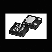
PMEG2010EPA NXP Semiconductors, PMEG2010EPA Datasheet

PMEG2010EPA
Related parts for PMEG2010EPA
PMEG2010EPA Summary of contents
Page 1
... Rev. 01 — 15 December 2009 1. Product profile 1.1 General description Planar Maximum Efficiency General Application (MEGA) Schottky barrier rectifier with an integrated guard ring for stress protection. PMEG2010EPA is encapsulated in an ultra thin SOT1061 leadless small Surface-Mounted Device (SMD) plastic package with medium power capability. 1.2 Features ...
Page 2
... NXP Semiconductors 2. Pinning information Table 2. Pin Ordering information Table 3. Type number PMEG2010EPA HUSON3 plastic thermal enhanced ultra thin small outline package; 4. Marking Table 4. Type number PMEG2010EPA 5. Limiting values Table 5. In accordance with the Absolute Maximum Rating System (IEC 60134). Symbol V ...
Page 3
... standard footprint Rev. 01 — 15 December 2009 PMEG2010EPA 1 A low V MEGA Schottky barrier rectifier F Min Max - 150 −55 +150 −65 +150 ...
Page 4
... FR4 PCB, mounting pad for cathode 1 cm Fig 2. Transient thermal impedance from junction to ambient as a function of pulse duration; typical values PMEG2010EPA_1 Product data sheet 1 A low V − − Rev. 01 — 15 December 2009 PMEG2010EPA MEGA Schottky barrier rectifier F 006aab625 (s) p 006aab626 ...
Page 5
... diode capacitance MHz reverse recovery time = mA Rev. 01 — 15 December 2009 PMEG2010EPA 1 A low V MEGA Schottky barrier rectifier F 006aab627 (s) p Min Typ Max - 280 - - 320 375 ...
Page 6
... F (1) T (2) T (3) T (4) T Fig 5. 350 C d (pF) 300 250 200 150 100 Rev. 01 — 15 December 2009 PMEG2010EPA 1 A low V MEGA Schottky barrier rectifier F 006aab629 (1) (2) ( 125 ° ° ° −40 °C ...
Page 7
... T (°C) amb (1) δ (2) δ kHz (3) δ kHz (4) δ kHz Fig 10. Average forward current as a function of Rev. 01 — 15 December 2009 PMEG2010EPA 1 A low V MEGA Schottky barrier rectifier F 006aab632 (1) (2) ( 125 °C ...
Page 8
... T (°C) amb T j (1) δ (2) δ kHz (3) δ kHz (4) δ kHz Fig 12. Average forward current as a function of solder point temperature; typical values Rev. 01 — 15 December 2009 PMEG2010EPA MEGA Schottky barrier rectifier F 006aab636 (1) (2) (3) ( 100 125 ...
Page 9
... F AV × δ at DC, and RMS M 1.3 0.35 0.25 1 1.05 0.95 0.3 3 0.2 1.6 1.4 2.1 1.9 Dimensions in mm Rev. 01 — 15 December 2009 PMEG2010EPA 1 A low V MEGA Schottky barrier rectifier duty cycle δ 006aaa812 Figure 9, 10, 11 and × δ with I defined as peak current with I defined as RMS current. ...
Page 10
... NXP Semiconductors 10. Packing information Table 8. The indicated -xxx are the last three digits of the 12NC ordering code. Type number PMEG2010EPA SOT1061 [1] For further information and the availability of packing methods, see 11. Soldering 2.3 Reflow soldering is the only recommended soldering method. Fig 15. Reflow soldering footprint SOT1061 ...
Page 11
... Revision history Table 9. Revision history Document ID Release date PMEG2010EPA_1 20091215 PMEG2010EPA_1 Product data sheet 1 A low V Data sheet status Change notice Product data sheet - Rev. 01 — 15 December 2009 PMEG2010EPA MEGA Schottky barrier rectifier F Supersedes - © NXP B.V. 2009. All rights reserved ...
Page 12
... Trademarks Notice: All referenced brands, product names, service names and trademarks are the property of their respective owners. http://www.nxp.com salesaddresses@nxp.com Rev. 01 — 15 December 2009 PMEG2010EPA MEGA Schottky barrier rectifier F © NXP B.V. 2009. All rights reserved ...
Page 13
... Please be aware that important notices concerning this document and the product(s) described herein, have been included in section ‘Legal information’. © NXP B.V. 2009. For more information, please visit: http://www.nxp.com For sales office addresses, please send an email to: salesaddresses@nxp.com Date of release: 15 December 2009 Document identifier: PMEG2010EPA_1 All rights reserved. ...


