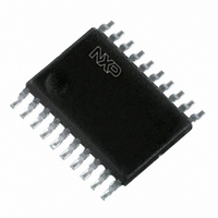
74LVT640PW,112 NXP Semiconductors, 74LVT640PW,112 Datasheet - Page 4

74LVT640PW,112
Manufacturer Part Number
74LVT640PW,112
Description
IC TRANSCEIVER 8BIT INV 20TSSOP
Manufacturer
NXP Semiconductors
Series
74LVTr
Datasheet
1.74LVT640DB112.pdf
(10 pages)
Specifications of 74LVT640PW,112
Logic Type
Transceiver, Inverting
Number Of Elements
1
Number Of Bits Per Element
8
Current - Output High, Low
32mA, 64mA
Voltage - Supply
2.7 V ~ 3.6 V
Operating Temperature
-40°C ~ 85°C
Mounting Type
Surface Mount
Package / Case
20-TSSOP
Lead Free Status / RoHS Status
Lead free / RoHS Compliant
Other names
568-3048-5
935213090112
935213090112
1. All typical values are at V
2. This is the increase in supply current for each input at the specified voltage level other than V
3. This parameter is valid for any V
4. Unused pins at V
5. This is the bus hold overdrive current required to force the input to the opposite logic state.
Philips Semiconductors
RECOMMENDED OPERATING CONDITIONS
DC ELECTRICAL CHARACTERISTICS
NOTES:
1998 Feb 19
SYMBOL
SYMBOL
SYMBOL
3.3V Octal transceiver with direction pin; inverting
(3-State)
I
transition time of 100 sec is permitted. This parameter is valid for T
I
PU/PD
HOLD
I
V
I
I
I
T
V
V
V
OFF
I
CCH
CCL
CCZ
V
I
V
I
I
amb
EX
I
OH
t/ v
OH
V
OL
OL
OL
I
CC
CC
IK
I
IH
IL
I
Input clamp voltage
High-level output voltage
Low-level output voltage
Input leakage current
Output off current
Bus Hold current A
Bus Hold current A
inputs
in uts
Current into an ouptut in the
High state when V
Power up/down 3-State
output current
Quiescent supply current
Additional supply current per
input pin
DC supply voltage
Input voltage
High-level input voltage
Input voltage
High-level output current
Low-level output current
Low-level output current; current duty cycle
Input transition rise or fall rate; Outputs enabled
Operating free-air temperature range
NO TAG
CC
PARAMETER
2
or GND.
3
CC
= 3.3V and T
O
> V
CC
CC
between 0V and 1.2V with a transition time of up to 10msec. From V
amb
PARAMETER
PARAMETER
V
V
V
V
V
V
V
V
V
V
V
V
V
V
V
V
V
V
V
V
OE/OE = Don’t care
V
V
V
V
Other inputs at V
CC
CC
CC
CC
CC
CC
CC
CC
CC
CC
CC
CC
CC
CC
CC
CC
CC
CC
O
CC
CC
CC
CC
CC
= 25 C.
= 5.5V; V
= 2.7V; I
= 2.7 to 3.6V; I
= 2.7V; I
= 3.0V; I
= 2.7V; I
= 2.7V; I
= 3.0V; I
= 3.0V; I
= 3.0V; I
= 0 or 3.6V; V
= 3.6V; V
= 3.6V; V
= 3.6V; V
= 3.6V; V
= 0V; V
= 3V; V
= 3V; V
= 0V to 3.6V; V
= 3.6V; Outputs High, V
= 3.6V; Outputs Low, V
= 3.6V; Outputs Disabled; V
= 3V to 3.6V; One input at V
1.2V; V
I
I
I
CC
IK
OH
OH
OL
OL
OL
OL
OL
or V
= 0.8V
= 2.0V
50%; f
O
I
I
I
I
= V
= 5.5V
= V
= 0
= –18mA
= 3.0V
= 0.5V to V
= 100 A
= 24mA
= 16mA
= 32mA
= 64mA
= –8mA
= –32mA
CC
O
TEST CONDITIONS
I
CC
CC
OH
= 0 to 4.5V
= 5.5V
CC
or GND
or GND
1kHz
= –100 A
= 3.6V
amb
4
CC
I
= +25 C only.
I
= GND or V
= GND or V
; V
I
I
CC
= GND or V
= GND or V
-0.6V,
CC,
CC,
I/O Data pins
Control pins
Control ins
I
I
O
CC,
CC
O
= 0
= 0
;
I
CC
O
= 0
or GND
MIN
–40
2.7
2.0
4
0
V
CC
Temp = -40 C to +85 C
CC
MIN
–75
LIMITS
2.4
2.0
75
500
-0.2
= 1.2V to V
LIMITS
V
TYP
CC
–150
–0.9
0.25
0.13
0.13
MAX
150
–32
+85
2.5
2.2
0.1
0.3
0.3
0.4
0.1
0.1
3.6
5.5
0.8
–1
60
15
0.1
32
64
10
1
1
1
3
-0.1
CC
1
74LVT640
Product specification
= 3.3V
MAX
–1.2
0.55
0.19
0.19
125
0.2
0.5
0.4
0.5
0.2
10
20
100
100
12
-5
1
1
UNIT
UNIT
0.3V a
ns/V
mA
mA
mA
V
V
V
V
C
UNIT
mA
mA
V
V
V
A
A
A
A
A


