74ALVC16245DL,112 NXP Semiconductors, 74ALVC16245DL,112 Datasheet
74ALVC16245DL,112
Specifications of 74ALVC16245DL,112
74ALVC16245DL
935187800112


Related parts for 74ALVC16245DL,112


74ALVC16245DL,112 Summary of contents
Page 1
Rev. 03 — 12 May 2004 1. General description The 74ALVC16245; 74ALVCH16245 is a 16-bit transceiver featuring non-inverting 3-state bus compatible outputs in both send and receive directions. The 74ALVC16245; 74ALVCH16245 features ...
Page 2
Philips Semiconductors 3. Quick reference data Table 1: Symbol PHL PLH I [ input frequency in MHz output frequency in MHz; ...
Page 3
Philips Semiconductors 5. Functional diagram Fig 1. Logic symbol. Fig 3. Bushold circuit. 9397 750 13117 Product data sheet 74ALVC16245; 74ALVCH16245 16-bit bus transceiver with direction pin; 3-state 1 24 1DIR 2DIR 47 1A0 1B0 2 46 1A1 1B1 3 ...
Page 4
Philips Semiconductors Fig 4. Logic diagram. 9397 750 13117 Product data sheet 74ALVC16245; 74ALVCH16245 16-bit bus transceiver with direction pin; 3-state 1DIR 1 1OE 1A0 47 1B0 1A1 46 1B1 1A2 44 1B2 1A3 43 1B3 1A4 41 1B4 1A5 ...
Page 5
Philips Semiconductors 6. Pinning information 6.1 Pinning Fig 5. Pin configuration. 6.2 Pin description Table 3: Pin 9397 750 13117 Product data sheet 74ALVC16245; 74ALVCH16245 16-bit bus transceiver with ...
Page 6
Philips Semiconductors Table 3: Pin ...
Page 7
Philips Semiconductors 7. Functional description 7.1 Function table Table 4: Input nOE [ HIGH voltage level L = LOW voltage level X = don’t care Z = high-impedance OFF-state. 8. Limiting values Table 5: In ...
Page 8
Philips Semiconductors 9. Recommended operating conditions Table 6: Symbol amb 10. Static characteristics Table 7: Static characteristics At recommended operating conditions; voltages are referenced to GND (ground = ...
Page 9
Philips Semiconductors Table 7: Static characteristics At recommended operating conditions; voltages are referenced to GND (ground = 0 V). Symbol Parameter I quiescent supply current CC I additional quiescent supply current CC given per data I/O pin with bushold I ...
Page 10
Philips Semiconductors 11. Dynamic characteristics Table 8: Dynamic characteristics At recommended operating conditions; voltages are referenced to GND (ground = 0 V); test circuit Symbol Parameter [ +85 C amb propagation delay ...
Page 11
Philips Semiconductors 12. Waveforms Fig 6. Input (nAn, nBn) to output (nBn, nAn) propagation delay times. Table 9: Supply voltage V CC < 2.7 V 2.7 V Fig 7. 3-state enable and disable times. Table 10: Supply voltage V CC ...
Page 12
Philips Semiconductors Fig 8. Load circuitry for switching times. Table 11: Supply voltage V CC < 2.7 V 2.7 V 3.6 V 9397 750 13117 Product data sheet 74ALVC16245; 74ALVCH16245 16-bit bus transceiver with direction pin; 3-state V I PULSE ...
Page 13
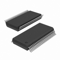
Philips Semiconductors 13. Package outline SSOP48: plastic shrink small outline package; 48 leads; body width 7 pin 1 index 1 e DIMENSIONS (mm are the original dimensions) A UNIT max. ...
Page 14
Philips Semiconductors TSSOP48: plastic thin shrink small outline package; 48 leads; body width 6 pin 1 index 1 DIMENSIONS (mm are the original dimensions). A UNIT max. 0.15 1.05 mm ...
Page 15
Philips Semiconductors 14. Revision history Table 12: Revision history Document ID Release date Data sheet status 74ALVC_ALVCH16245_3 20040512 • Modifications: The format of this data sheet has been redesigned to comply with the current presentation and information standard of Philips ...
Page 16
Philips Semiconductors 15. Data sheet status [1] Level Data sheet status Product status I Objective data Development II Preliminary data Qualification III Product data Production [1] Please consult the most recently issued data sheet before initiating or completing a design. ...
Page 17
Philips Semiconductors 19. Contents 1 General description . . . . . . . . . . . . . . . . . . . . . . 1 2 Features . . . . . . . . ...