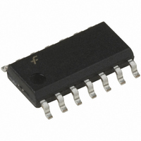
74LVX74M Fairchild Semiconductor, 74LVX74M Datasheet - Page 5

74LVX74M
Manufacturer Part Number
74LVX74M
Description
IC FLIP FLOP DUAL D-TYPE 14-SOIC
Manufacturer
Fairchild Semiconductor
Series
74LVXr
Type
D-Typer
Datasheet
1.74LVX74MTCX.pdf
(9 pages)
Specifications of 74LVX74M
Function
Set(Preset) and Reset
Output Type
Differential
Number Of Elements
2
Number Of Bits Per Element
1
Frequency - Clock
95MHz
Delay Time - Propagation
5.7ns
Trigger Type
Positive Edge
Current - Output High, Low
4mA, 4mA
Voltage - Supply
2 V ~ 3.6 V
Operating Temperature
-40°C ~ 85°C
Mounting Type
Surface Mount
Package / Case
14-SOIC (3.9mm Width), 14-SOL
Flip-flop Type
D
Propagation Delay
8.2ns
Frequency
145MHz
Output Current
4mA
Ic Output Type
Complementary
Supply Voltage Range
2V To 3.6V
Logic Case Style
SOIC
Rohs Compliant
No
Logic Family
LVX
Technology
CMOS
Number Of Bits
2
Number Of Elements
2
Clock-edge Trigger Type
Positive-Edge
Polarity
Invert/Non-Invert
Operating Supply Voltage (typ)
2.5/3.3V
Package Type
SOIC N
Propagation Delay Time
19.1ns
Low Level Output Current
4mA
High Level Output Current
-4mA
Frequency (max)
80MHz
Operating Supply Voltage (min)
2V
Operating Supply Voltage (max)
3.6V
Operating Temp Range
-40C to 85C
Operating Temperature Classification
Industrial
Mounting
Surface Mount
Pin Count
14
Lead Free Status / RoHS Status
Lead free / RoHS Compliant
Available stocks
Company
Part Number
Manufacturer
Quantity
Price
Company:
Part Number:
74LVX74MSCX
Manufacturer:
TOSHIBA
Quantity:
15 745
Part Number:
74LVX74MTCX
Manufacturer:
FAIRCHILD/仙童
Quantity:
20 000
Company:
Part Number:
74LVX74MX
Manufacturer:
AMP
Quantity:
4 823
Part Number:
74LVX74MX
Manufacturer:
FAIRCHILD/仙童
Quantity:
20 000
©1993 Fairchild Semiconductor Corporation
74LVX74 Rev. 1.4.0
AC Electrical Characteristics
Note:
3. Parameter guaranteed by design t
Capacitance
Note:
4. C
t
OSLH
t
t
Symbol
Symbol
consumption without load.
Average operating current can be obtained by the eqation: I
PLH
PLH
PD
t
f
C
REC
MAX
C
t
t
t
, t
, t
W
, t
S
H
PD
IN
is defined as the value of the internal equivalent capacitance which is calculated from the operating current
PHL
PHL
OSHL
Propagation Delay,
CP
Propagation Delay,
C
CP
Width
Setup Time, D
Hold Time, D
Recovery Time,
CP
Maximum Clock
Frequency
Output to Output Skew
Input Capacitance
Power Dissipation Capacitance
Dn
n
n
n
to S
to Q
or C
or S
Parameter
Dn
Dn
n
Dn
or Q
to Q
to CP
or S
n
n
to CP
n
n
to CP
Dn
Parameter
or Q
n
Pulse
n
n
n
OSLH
(3)
3.3 ± 0.3
3.3 ± 0.3
3.3 ± 0.3
3.3 ± 0.3
3.3 ± 0.3
3.3 ± 0.3
3.3 ± 0.3
V
CC
|t
2.7
2.7
2.7
2.7
2.7
2.7
2.7
2.7
3.3
PLHm
(4)
(V)
–t
PLHn
C
L
|, t
15
50
15
50
15
50
15
50
15
50
15
50
50
(pF)
5
OSHL
CC(opr.)
Min.
Min.
|t
8.5
8.0
5.5
0.5
0.5
6.5
5.0
55
45
95
60
PHLm
T
6
A
=
T
Typ.
C
-------------------------------------------------------- -
A
–t
25
+25°C
4
PD
PHLn
Typ.
10.9
135
145
7.3
9.8
5.7
8.2
8.4
6.6
60
85
9.1
2 per F F
+25°C
V
|
CC
Max.
10
Max.
18.5
13.2
19.1
13.6
15.6
10.1
1.5
1.5
15
9.7
f
IN
T
I
Min.
CC
A
T
Min.
A
1.0
1.0
1.0
1.0
1.0
1.0
1.0
1.0
9.5
6.5
0.5
0.5
7.5
5.0
10
50
40
80
50
+85°C
7
–40°C to
+85°C
–40°C to
Max.
Max.
10
18.5
11.5
18.5
15.5
1.5
1.5
22
15
22
12
www.fairchildsemi.com
Units
Units
MHz
pF
pF
ns
ns
ns
ns
ns
ns
ns


