CBT3244ADB,118 NXP Semiconductors, CBT3244ADB,118 Datasheet - Page 16
CBT3244ADB,118
Manufacturer Part Number
CBT3244ADB,118
Description
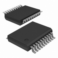
IC BUS SWITCH OCTAL 8BIT 20SSOP
Manufacturer
NXP Semiconductors
Series
74CBTr
Type
Bus Switchr
Datasheet
1.CBT3244ADB118.pdf
(18 pages)
Specifications of CBT3244ADB,118
Circuit
4 x 1:1
Independent Circuits
2
Current - Output High, Low
15mA, 64mA
Voltage Supply Source
Single Supply
Voltage - Supply
4.5 V ~ 5.5 V
Operating Temperature
-40°C ~ 85°C
Mounting Type
Surface Mount
Package / Case
20-SSOP
Lead Free Status / RoHS Status
Lead free / RoHS Compliant
Other names
935276001118
CBT3244ADB-T
CBT3244ADB-T
CBT3244ADB-T
CBT3244ADB-T


Philips Semiconductors
14. Abbreviations
15. Revision history
Table 11:
9397 750 13362
Product data sheet
Document ID
CBT3244_2
Modifications:
CBT3244A_1
Revision history
Release date
20050915
20040526
•
•
•
•
[4]
[5]
[6]
[7]
[8]
[9]
Table 10:
Acronym
CDM
ESD
HBM
MM
PRR
TTL
The format of this data sheet has been redesigned to comply with the new presentation and
information standard of Philips Semiconductors.
added DHVQFN20 package option (affects
information”,
Section 2 “Features” on page
2000 V HBM ...’
added
These packages are not suitable for wave soldering. On versions with the heatsink on the bottom side, the
solder cannot penetrate between the printed-circuit board and the heatsink. On versions with the heatsink
on the top side, the solder might be deposited on the heatsink surface.
If wave soldering is considered, then the package must be placed at a 45 angle to the solder wave
direction. The package footprint must incorporate solder thieves downstream and at the side corners.
Wave soldering is suitable for LQFP, QFP and TQFP packages with a pitch (e) larger than 0.8 mm; it is
definitely not suitable for packages with a pitch (e) equal to or smaller than 0.65 mm.
Wave soldering is suitable for SSOP, TSSOP, VSO and VSSOP packages with a pitch (e) equal to or larger
than 0.65 mm; it is definitely not suitable for packages with a pitch (e) equal to or smaller than 0.5 mm.
Image sensor packages in principle should not be soldered. They are mounted in sockets or delivered
pre-mounted on flex foil. However, the image sensor package can be mounted by the client on a flex foil by
using a hot bar soldering process. The appropriate soldering profile can be provided on request.
Hot bar soldering or manual soldering is suitable for PMFP packages.
Section 14 “Abbreviations” on page 16
Abbreviations
Data sheet status
Product data sheet
Product data sheet
Section 5 “Pinning
Description
Charged Device Model
ElectroStatic Discharge
Human Body Model
Machine Model
Pulse Rate Repetition
Transistor-Transistor Logic
Rev. 02 — 15 September 2005
1, 6th bullet: changed from ‘exceeds 1000 V HBM ...’ to ‘exceeds
information”, and
Change notice
-
-
Section 2
Octal bus switch with quad output enables
Section 12 “Package outline”
“Features”,
Doc. number
9397 750 13362
9397 750 13281
© Koninklijke Philips Electronics N.V. 2005. All rights reserved.
Section 3 “Ordering
CBT3244A
Supersedes
CBT3244A_1
-
16 of 18
Related parts for CBT3244ADB,118
Image
Part Number
Description
Manufacturer
Datasheet
Request
R

Part Number:
Description:
IC BUS SWITCH OCTAL 8BIT 20SOIC
Manufacturer:
NXP Semiconductors
Datasheet:
Part Number:
Description:
IC BUS SWITCH OCT 20-SOIC
Manufacturer:
NXP Semiconductors
Datasheet:
Part Number:
Description:
Bus Switch 2-Element 4-IN 20-Pin SO Tube
Manufacturer:
NXP Semiconductors
Datasheet:

Part Number:
Description:
Octal bus switch with quad output enables
Manufacturer:
PHILIPS [NXP Semiconductors]
Datasheet:
Part Number:
Description:
NXP Semiconductors designed the LPC2420/2460 microcontroller around a 16-bit/32-bitARM7TDMI-S CPU core with real-time debug interfaces that include both JTAG andembedded trace
Manufacturer:
NXP Semiconductors
Datasheet:

Part Number:
Description:
NXP Semiconductors designed the LPC2458 microcontroller around a 16-bit/32-bitARM7TDMI-S CPU core with real-time debug interfaces that include both JTAG andembedded trace
Manufacturer:
NXP Semiconductors
Datasheet:
Part Number:
Description:
NXP Semiconductors designed the LPC2468 microcontroller around a 16-bit/32-bitARM7TDMI-S CPU core with real-time debug interfaces that include both JTAG andembedded trace
Manufacturer:
NXP Semiconductors
Datasheet:
Part Number:
Description:
NXP Semiconductors designed the LPC2470 microcontroller, powered by theARM7TDMI-S core, to be a highly integrated microcontroller for a wide range ofapplications that require advanced communications and high quality graphic displays
Manufacturer:
NXP Semiconductors
Datasheet:
Part Number:
Description:
NXP Semiconductors designed the LPC2478 microcontroller, powered by theARM7TDMI-S core, to be a highly integrated microcontroller for a wide range ofapplications that require advanced communications and high quality graphic displays
Manufacturer:
NXP Semiconductors
Datasheet:
Part Number:
Description:
The Philips Semiconductors XA (eXtended Architecture) family of 16-bit single-chip microcontrollers is powerful enough to easily handle the requirements of high performance embedded applications, yet inexpensive enough to compete in the market for hi
Manufacturer:
NXP Semiconductors
Datasheet:
Part Number:
Description:
The XA-S3 device is a member of Philips Semiconductors? XA(eXtended Architecture) family of high performance 16-bitsingle-chip microcontrollers
Manufacturer:
NXP Semiconductors
Datasheet:

Part Number:
Description:
The NXP BlueStreak LH75401/LH75411 family consists of two low-cost 16/32-bit System-on-Chip (SoC) devices
Manufacturer:
NXP Semiconductors
Datasheet:
Part Number:
Description:
The NXP LPC3130/3131 combine an 180 MHz ARM926EJ-S CPU core, high-speed USB2
Manufacturer:
NXP Semiconductors
Datasheet:
Part Number:
Description:
The NXP LPC3141 combine a 270 MHz ARM926EJ-S CPU core, High-speed USB 2
Manufacturer:
NXP Semiconductors