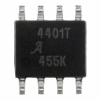
A4401KL-T Allegro Microsystems Inc, A4401KL-T Datasheet

A4401KL-T
Specifications of A4401KL-T
Related parts for A4401KL-T
A4401KL-T Summary of contents
Page 1
Automotive Quasi-Resonant Flyback Control IC Features and Benefits ▪ Multiple output regulator ▪ input supply ▪ Low EMI conducted and radiated emissions ▪ Adaptive quasi-resonant turn on/off control ▪ Minimal number of external components ▪ Enable ...
Page 2
... A4401 Automotive Quasi-Resonant Flyback Control IC Selection Guide Part Number A4401KLTR-T Tape and reel, 3000 pieces/reel Absolute Maximum Ratings* Characteristic VIN Pin Voltage LX Pin Voltage ISS Pin Voltage EN Pin Voltage VA Pin Voltage ESD Rating – Human Body Model ESD Rating – Charged Device Model ...
Page 3
A4401 Automotive Quasi-Resonant Flyback Control IC Optional V BAT EMI Filter 7 to 40V VIN Linear Adaptive turn-on control Control Enable Logic kΩ Shutdown UVLO Fault TSD GND VIN COMP LX ...
Page 4
A4401 Automotive Quasi-Resonant Flyback Control IC 1,2 ELECTRICAL CHARACTERISTICS Characteristics General VIN Quiescent Current LX Leakage Current LX Input Bias Current Minimum Frequency Soft Start Gate Drive Drive High Voltage, V > Drive High Voltage ...
Page 5
A4401 Automotive Quasi-Resonant Flyback Control IC Basic Operation A peak current-mode control scheme is used to regu- late one of the converter outputs, which will typically be the highest output voltage. The regulated output voltage is potentially divided down and ...
Page 6
A4401 Automotive Quasi-Resonant Flyback Control IC In the event of an overload, the current demand signal produced by the Gm amplifier restricts the output cur- rent by introducing pulse-by-pulse current limiting. Regulation Voltage The feedback resistors, R5 and R6, determine ...
Page 7
A4401 Automotive Quasi-Resonant Flyback Control IC If there is a special requirement for larger output capacitors, and the onboard soft start is insufficient, an external soft start can be introduced. This can be implemented by “pulling” down the amplifier output ...
Page 8
A4401 Automotive Quasi-Resonant Flyback Control IC The turn-on losses are Switching Turn-On Losses determined by the amount of energy the resonant capacitor, C11, has to discharge into the MOSFET. At low battery voltage, the resonant swing should force the volts ...
Page 9
A4401 Automotive Quasi-Resonant Flyback Control IC for more information). The current that flows in and out of the capacitor is similar to the current that flows through the corresponding rectifier diode. Worst case power dissipation due to the ESR will ...
Page 10
A4401 Automotive Quasi-Resonant Flyback Control IC • Magnetics sizing can be determined using techniques such as area product or geometric product fol- lowing manufacturers guidelines, usually in the form of nomograms. To simplify the design process, the resonant ...
Page 11
A4401 Automotive Quasi-Resonant Flyback Control IC then: μ × (approx Because of flux fringing effects, the above air gap should be modified, according to the following formu- las. Given: (approx) ⎛ ⎜ ...
Page 12
A4401 Automotive Quasi-Resonant Flyback Control IC where I is the maximum load current, and D'(max) OUT is the duty cycle, limited to 0.3. Then the rms current in the winding is: ⎛ D' ⎜ ⎜ × RMS ...
Page 13
A4401 Automotive Quasi-Resonant Flyback Control IC filtering imperative that the “power loop” formed by the input filter, primary winding, MOSFET, Q1, and sense resistor is as short and “tight” as possible. This means components should be placed as ...
Page 14
A4401 Automotive Quasi-Resonant Flyback Control IC It can be seen that at MOSFET turn-on there is a considerable sinusoidal ringing on the voltage sense, in the region of 3 MHz. In addition, there is a con- siderable ringing during the ...
Page 15
A4401 Automotive Quasi-Resonant Flyback Control IC A simple low-loss R-C snubber can be deployed to dampen these oscillations so, follow these sim- ple steps to determine the component values required: 1. Measure the voltage resonant frequency, f the ...
Page 16
A4401 Automotive Quasi-Resonant Flyback Control IC The capacitance selection has been dealt with in the Input Capacitor Selection section. In terms of select- ing an inductance, generally the higher the inductance the better as far as noise rejection of the ...
Page 17
A4401 Automotive Quasi-Resonant Flyback Control IC 4.90 ±0. 0.20 C 0.41 ±0.10 Copyright ©2007-2008, Allegro MicroSystems, Inc. The products described here are manufactured under one or more U.S. patents or U.S. patents pending. Allegro MicroSystems, ...


