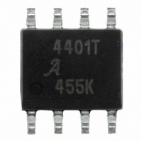
A4401KL-T Allegro Microsystems Inc, A4401KL-T Datasheet - Page 11

A4401KL-T
Manufacturer Part Number
A4401KL-T
Description
IC QUASI FLYBACK CONVERTER 8SOIC
Manufacturer
Allegro Microsystems Inc
Datasheet
1.A4401KLTR-T.pdf
(17 pages)
Specifications of A4401KL-T
Display Type
Vacuum Fluorescent (VF)
Current - Supply
2.3mA
Voltage - Supply
7 V ~ 40 V
Operating Temperature
-40°C ~ 125°C
Mounting Type
Surface Mount
Package / Case
8-SOIC (3.9mm Width)
Lead Free Status / RoHS Status
Lead free / RoHS Compliant
Interface
-
Configuration
-
Digits Or Characters
-
A4401
then:
Because of flux fringing effects, the above air gap
should be modified, according to the following formu-
las. Given:
where l
mate air gap, and G is the bobbin width (the effective
winding width).
then the total air gap can now be found:
Note that most ferrite core manufacturers provide a
limited number of air gap sizes. It is therefore recom-
mended to select a standard size. Size is indicated
in terms of the Al factor, which is expressed in L/N
units. The Al factor can be derived from the above two
formulae.
To minimize flux leakage effects, it is recommended
that the air gap should be located on the center limb.
If, however, a distributed air gap is used, the air gap
figure should be divided by two.
Some applications require an AC filament output.
Typically this may be a center tapped winding with
the center tap held at some bias voltage. During the
MOSFET off-time, the output voltage of the control
winding is simply reflected through the turns ratio of
the magnetics.
During the on-time of the MOSFET, the windings are
driven as a forward converter because there is no rec-
tifying diode to isolate this action. The voltage during
this interval is simply the battery voltage transformed
by the turns ratio of the filament winding and the pri-
mary winding. This means that as the battery voltage
varies, there will be a variation in the filament voltage.
However, this variation will be less than those aris-
g
(approx) is the previously calculated approxi-
F =
I
I
g
g
(approx) =
I
=
g
(approx)
I
A
g
(approx) × (1 + F)
½
e
× ln
μ
O
× A
⎛
⎜ ⎜
⎝
Automotive Quasi-Resonant Flyback Control IC
L
I
g
P
e
(approx)
2 × G
× N
P
²
.
⎞
⎟ ⎟
⎠
.
.
(27)
(28)
(29)
2
ing in other converter topologies because, during the
MOSFET off-time, the voltage is regulated.
The voltage amplitude across the filament winding is:
where:
It is probably desirable to optimize the filament volt-
age at nominal battery conditions; for example, at
V
Due to the low voltage out, the number of integer turn
combinations is limited. So, the filament voltage may
not be exact. The turns range may only be 2 or 3.
The magnetic wire sizing for each winding is deter-
mined by the ampere-turns ratio as a proportion of the
total ampere-turns of all the windings. The amount of
bobbin area available for the windings is influenced by
the amount of insulation required, the winding con-
struction technique, and the packing density of the cir-
cular wire. A conservative utilization factor is 0.5, that
is, 50% of the bobbin window area filled with copper.
The rms current of each winding has to be determined.
The worst case condition is at minimum input voltage
and maximum load.
The primary winding current is identical to the current
flowing in the current sense resistor (see the Current
Sense Resistor Selection section). The current in each
of the other output windings can be found as follows.
Given:
N
N
output winding, and
V
output.
BAT
SF
S1
OUT1
= 13.5 V.
is the number of turns on the main controlled
is the number of turns on the filament winding,
is the output voltage of the main controlled
V
FIL
=
V
BAT
I
PK
×
115 Northeast Cutoff, Box 15036
Allegro MicroSystems, Inc.
Worcester, Massachusetts 01615-0036 (508) 853-5000
www.allegromicro.com
=
N
N
SF
P
2 × I
D'(max)
+ V
OUT
OUT1
×
,
N
N
SF
S1
,
(30)
(31)
11


