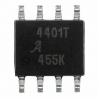
A4401KL-T Allegro Microsystems Inc, A4401KL-T Datasheet - Page 14

A4401KL-T
Manufacturer Part Number
A4401KL-T
Description
IC QUASI FLYBACK CONVERTER 8SOIC
Manufacturer
Allegro Microsystems Inc
Datasheet
1.A4401KLTR-T.pdf
(17 pages)
Specifications of A4401KL-T
Display Type
Vacuum Fluorescent (VF)
Current - Supply
2.3mA
Voltage - Supply
7 V ~ 40 V
Operating Temperature
-40°C ~ 125°C
Mounting Type
Surface Mount
Package / Case
8-SOIC (3.9mm Width)
Lead Free Status / RoHS Status
Lead free / RoHS Compliant
Interface
-
Configuration
-
Digits Or Characters
-
A4401
It can be seen that at MOSFET turn-on there is a
considerable sinusoidal ringing on the voltage sense,
in the region of 3 MHz. In addition, there is a con-
siderable ringing during the MOSFET turn-off, in the
region of 6 MHz. These ringing effects are caused by
the primary-to-secondary leakage inductance interact-
ing with parasitic capacitance. These noise sources
will probably have an impact on the conducted emis-
sions and should therefore be suppressed.
By rescaling the magnetics so that 0 V switching is
achieved with V
almost completely damped, as shown in Figure 6.
Because the resonant capacitor, C11, had discharged
to 0 V before switching, there was effectively little
energy left.
The turn-off noise is also improved dramatically as
well. It can be seen that the ringing amplitude is lower,
dampens more quickly, and the ringing frequency
is higher making it easier to snub (see the Radiated
Emissions on the LX Node subsection). The reason for
Figure 5. Voltages with 0 V switching of Q1 at V
V
RSENSE
V
LX
BAT
MOSFET
Turn-On
= 13.5 V, the turn-on ringing is
MOSFET
Turn-Off
Automotive Quasi-Resonant Flyback Control IC
BAT
of 7 V
this effect is that a lower step-up ratio is required to
achieve the output voltage. This improves the mag-
netic coupling coefficient and therefore the leakage
inductance is reduced.
Running the system with a lower turns ratio means
that the duty cycle is greater. The advantage of this
is that the peak current is lower, resulting in lower
turn-off switching losses and reduced harmonics of the
input current, thus reducing the conducted emissions.
Radiated Emissions on LX Node
of radiated emissions is turning off the MOSFET. A
resonance is set up between the leakage inductance
of the magnetics and the parasitic capacitance on the
LX node. Assuming the magnetics are well designed
in terms of reducing leakage inductance, this reso-
nance should occur in the region of tens of megahertz.
Another potential source of radiated emissions is
turning off the output rectifying diodes. The following
procedure can be applied to address both issues.
Figure 6. Voltages with 0 V switching of Q1 at V
MOSFET
Turn-On
V
RSENSE
V
LX
MOSFET
Turn-Off
115 Northeast Cutoff, Box 15036
Allegro MicroSystems, Inc.
Worcester, Massachusetts 01615-0036 (508) 853-5000
www.allegromicro.com
A potential source
BAT
of 13.5 V
14


