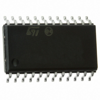
STP16CPS05MTR STMicroelectronics, STP16CPS05MTR Datasheet

STP16CPS05MTR
Specifications of STP16CPS05MTR
Available stocks
Related parts for STP16CPS05MTR
STP16CPS05MTR Summary of contents
Page 1
... LEDs. The auto power shut-down and auto power-ON feature allows the device to save power without any external intervention. Table 1. Device summary Order codes STP16CPS05MTR STP16CPS05TTR STP16CPS05XTTR STP16CPS05PTR January 2010 with auto power saving QSOP-24 TSSOP24 The output current setup time (typ), thus improving the system performance ...
Page 2
Contents Contents 1 Summary description . . . . . . . . . . . . . . . . . . . . . . . . . . . . . . . . . . . ...
Page 3
STP16CPS05 1 Summary description Table 2. Typical current accuracy Output voltage ≥ 1.3 V 1.1 Pin connection and description Figure 1. Pin connection Note: The exposed pad should be electrically connected to a metal land electrically isolated or connected to ...
Page 4
Electrical ratings 2 Electrical ratings 2.1 Absolute maximum ratings Stressing the device above the rating listed in the “absolute maximum ratings” table may cause permanent damage to the device. These are stress ratings only and operation of the device at ...
Page 5
STP16CPS05 2.3 Recommended operating conditions Table 6. Recommended operating conditions at 25 °C Symbol Parameter V Supply voltage DD V Output voltage O I Output current O I Output current OH I Output current OL V Input voltage IH V ...
Page 6
Electrical characteristics 3 Electrical characteristics Table 7. Electrical characteristics (V specified) Symbol V Input voltage high level IH V Input voltage low level IL I Output leakage current OH Output voltage V OL (Serial-OUT) Output voltage V OH (Serial-OUT) I ...
Page 7
STP16CPS05 Table 8. Switching characteristics (V Symbol Parameter Propagation delay time, t PLH1 CLK-OUTn Propagation delay time, t PLH2 LE-OUTn Propagation delay time, t PLH3 OE-OUTn Propagation delay ...
Page 8
Equivalent circuit and outputs 4 Equivalent circuit and outputs Figure 2. OE terminal Figure 3. LE terminal Figure 4. CLK, SDI terminal 8/27 Doc ID 12569 Rev 6 STP16CPS05 ...
Page 9
STP16CPS05 Figure 5. SDO terminal Figure 6. Block diagram Equivalent circuit and outputs Doc ID 12569 Rev 6 9/27 ...
Page 10
Timing diagrams 5 Timing diagrams Table 9. Truth table CLOCK Note: OUTn = ON when OUTn = OFF when Figure 7. Timing diagram Note: 1 Latch and output ...
Page 11
STP16CPS05 Table 10. Enable IO: shut-down truth table CLOCK Note: At the power-up the device starts in shut-down mode. Figure 8. Clock, serial-in, serial-out SDI ........... SDI ............ SDI All = L No ...
Page 12
Timing diagrams Figure 9. Clock, serial-in, latch, enable, outputs Figure 10. Outputs 12/27 Doc ID 12569 Rev 6 STP16CPS05 ...
Page 13
STP16CPS05 6 Typical characteristics Figure 11. Output current-R Table 11. Output current-R resistor EXT resistor EXT Rext (Ω) 976 780 652 560 488 433 389 354 325 300 278 259 241 229 215 Doc ID 12569 Rev 6 Typical characteristics ...
Page 14
Typical characteristics Figure 12. Output current vs ± ΔI Figure 13. I SET 14/27 (%) OL vs drop out voltage (V ) drop Doc ID 12569 Rev 6 STP16CPS05 ...
Page 15
STP16CPS05 Figure 14. I ON\OFF Figure 15. Auto power saving Note: Auto power-saving feature minimizes the quiescent current if no active data is detected on the latches and auto-power-up the ...
Page 16
Typical characteristics Figure 16. First output ON after switching from auto power saving to normal mode operating condition Note: When the device goes from auto power saving to normal operative condition, the first output that switch ON shows TON condition ...
Page 17
STP16CPS05 7 Test circuit Figure 17. DC characteristic Figure 18. AC characteristic Doc ID 12569 Rev 6 Test circuit 17/27 ...
Page 18
Test circuit Figure 19. Typical application schematic C = 10μF Note: V will be determined by the V L Table 12. Turn ON output current (1) characteristics 1. Reference level for the T characteristics is 50 signal to ...
Page 19
STP16CPS05 8 Package mechanical data In order to meet environmental requirements, ST offers these devices in different grades of ® ECOPACK packages, depending on their level of environmental compliance. ECOPACK specifications, grade definitions and product status are available at: www.st.com. ...
Page 20
Package mechanical data Figure 20. QSOP-24 package dimensions 20/27 Doc ID 12569 Rev 6 STP16CPS05 ...
Page 21
STP16CPS05 Table 15. TSSOP24 mechanical data Dim Figure 21. TSSOP24 package dimensions mm. Min Typ Max 1.1 0.05 0.15 0.9 0.19 0.30 0.09 0.20 7.7 7.9 4.3 4.5 0.65 ...
Page 22
Package mechanical data Table 16. Tape and reel TSSOP24 Dim Figure 22. Reel dimensions 22/27 mm. Min Typ Max 330 12.8 13.2 20.2 60 22.4 6.8 7 8.2 8.4 1.7 ...
Page 23
STP16CPS05 Table 17. SO-24 mechanical data Dim Figure 23. SO-24 package dimensions mm. Min Typ Max 2.65 0.1 0.2 2.45 0.35 0.49 0.23 0.32 0.5 15.20 ...
Page 24
Package mechanical data Table 18. Tape and reel SO-24 Dim Figure 24. Reel dimensions 24/27 mm. Min Typ Max 330 12.8 13.2 20.2 60 30.4 10.8 11.0 15.7 15.9 2.9 ...
Page 25
STP16CPS05 Table 19. TSSOP24 exposed pad Dim Figure 25. TSSOP24 dimensions mm Min Typ Max 1.2 0.15 0.8 1 1.05 0.19 0.30 0.09 0.20 7.7 7.8 7.9 ...
Page 26
Revision history 9 Revision history Table 20. Document revision history Date 28-Jul-2006 22-Dec-2006 17-May-2007 10-Jul-2007 28-Feb-2008 19-Jan-2010 26/27 Revision 1 First release 2 Final datasheet 3 Updated Table 8 on page 7 4 Updated Table 9: Truth table on page ...
Page 27
... STP16CPS05 Information in this document is provided solely in connection with ST products. STMicroelectronics NV and its subsidiaries (“ST”) reserve the right to make changes, corrections, modifications or improvements, to this document, and the products and services described herein at any time, without notice. All ST products are sold pursuant to ST’s terms and conditions of sale. ...


