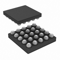
LP5526TL/NOPB National Semiconductor, LP5526TL/NOPB Datasheet - Page 16

LP5526TL/NOPB
Manufacturer Part Number
LP5526TL/NOPB
Description
IC LED DRVR WT/RGB BCKLT 25-USMD
Manufacturer
National Semiconductor
Series
PowerWise®r
Type
Backlight, White LED, RGB (I²C Interface)r
Datasheet
1.LP5526TLNOPB.pdf
(32 pages)
Specifications of LP5526TL/NOPB
Constant Current
Yes
Topology
PWM, Step-Up (Boost)
Number Of Outputs
5
Internal Driver
Yes
Type - Primary
Backlight, Light Management Unit (LMU)
Type - Secondary
RGB, White LED
Frequency
1MHz
Voltage - Supply
3 V ~ 5.5 V
Voltage - Output
8 V ~ 20 V
Mounting Type
Surface Mount
Package / Case
25-MicroSMD
Operating Temperature
-30°C ~ 85°C
Current - Output / Channel
150mA
Internal Switch(s)
Yes
Efficiency
88%
For Use With
LP5526TLEV - BOARD EVAL LP5526 LMU LED DRIVER
Lead Free Status / RoHS Status
Lead free / RoHS Compliant
Other names
LP5526TLTR
www.national.com
When RLED, GLED and BLED are connected together as in
Typical Application 1, flash current can be adjusted with
8.33% step in constant current mode by changing RGB max
current register values as seen on following table. Note that
0% means that appropriate output is turned off by setting
RSW, GSW or BSW bit to 0.
I
R
100
25
50
75
[%]
0
0
0
0
0
0
0
0
I
G
100
100
100
100
100
25
50
75
0
0
0
0
[%]
I
B
100
100
100
100
100
100
100
100
100
25
50
75
[%]
Total current [%]
16.67
25.00
33.33
41.67
50.00
58.33
66.67
75.00
83.33
91.67
8.33
100
Using Flash Mode
16
3. Using Flash Mode
In this mode Flash is triggered with external PWM pin and pre-
flash brightness is adjusted by adjusting the RGB max current
values. After flash pulse flash led will be shut down.
•
•
•
•
•
•
•
•
Note: EN_FLASH bit must be set low, and then high again
before it is possible to make a new flash pulse.
Write the pre-flash current values to RGB max current
register
Enable RGB functions and disable PWM mode (EN_RGB
= 1, RGB_PWM = 0)
Enable flash mode (EN_FLASH = 1), make sure GPIO[0]/
PWM pin is in low state
Enable external PWM pin (EN_PWM_PIN = 1)
Start pre-flash by switching on the LEDs (RSW = 1, GSW
= 1, BSW = 1). Pre-flash brightness can be affected also
by setting on only one or two LEDs
Use EN_EXT_R_PWM, EN_EXT_G_PWM and
EN_EXT_B_PWM bits to select which LED outputs are
used for flash
Start flash pulse by setting GPIO[0]/PWM pin high and
stop it by setting GPIO[0]/PWM pin low
During the flash pulse the LED outputs with
EN_EXT_x_PWM bit enabled give out maximum current,
regardless of RGB max current register value or XSW
values
20179704


